1. History of Serial Ports
First of all, the serial port is an essential tool for anyone working with hardware and embedded software, especially when debugging a system with an MCU or CPU. During the debugging process, the first thing we usually do is to light up the GPIO, and the second is to establish a connection through the serial port.
The serial port is a very versatile device interface, commonly used in instrumentation and communication interfaces, often for remote data collection or remote control. The development of serial ports is relatively simple, making it one of the favorite interfaces among many engineers.
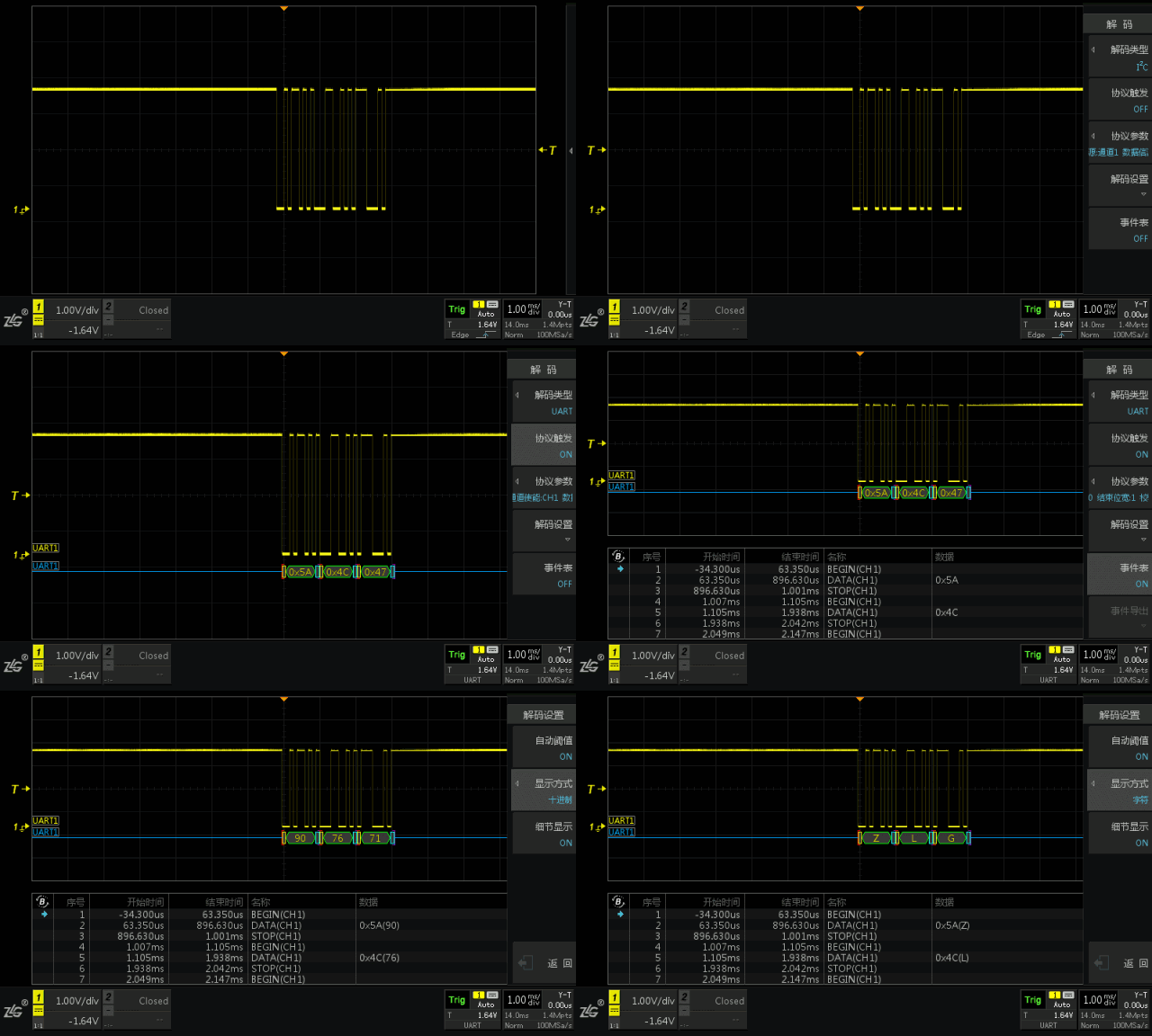
After completing the GPIO lighting, we generally hope to achieve the function of serial port printing, which allows us to print out some register information for debugging purposes.
Due to my personal experience, I could write a book about serial ports! It should be no less than 200 pages.
In 2008, when I first joined Huawei, I encountered a unique historical period where various players were competing in the embedded field.
1. Intel and AMD boldly claimed that the X86 system was entering the embedded field to capture the PowerPC market. (Later, Intel succeeded, as general-purpose servers dominated almost all telecom core-side devices—blade servers, rack servers).
2. At that time, MIPS, ARM, and PowerPC were still closely matched, but multi-core ARM was immature and could not be widely used in the telecom field. MIPS gradually faded due to its poor quality performance despite its excellent cost-performance ratio and high performance.
3. PowerPC, under pressure from other processors, also began to launch multi-core processors.
My job at that time was to participate in the circuit development of X86 processors as embedded systems. I encountered a problem: the traditional X86 architecture had evolved very maturely as a PC. The hardware structure of PCs is significantly different from that of embedded SoCs.
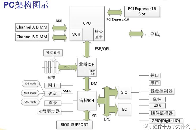
Under the CPU is the Northbridge responsible for high-speed peripherals, and below the Northbridge (Southbridge) is the Southbridge responsible for low-speed interface peripherals, along with a Super I/O responsible for even lower-speed peripherals.
Super I/O is short for Super Input/Output.
The Super I/O chip is generally located at the lower left or upper left of the motherboard. The main chips used are Winbond and ITE, which provide control processing functions for standard I/O interfaces on the motherboard. The term “super” refers to its integration of processing functions for PS/2 keyboard, PS/2 mouse, serial COM, and parallel LPT interfaces, all of which are slow I/O devices in computers. They are all located at the back right of the motherboard. Its main functions include processing serial data transmitted from devices such as keyboards, mice, and serial interfaces, converting them into parallel data, and also handling the transmission and processing of data from parallel interfaces and floppy drive interfaces. Super I/O connects to the Southbridge via a simplified PCI bus called the LPC bus.
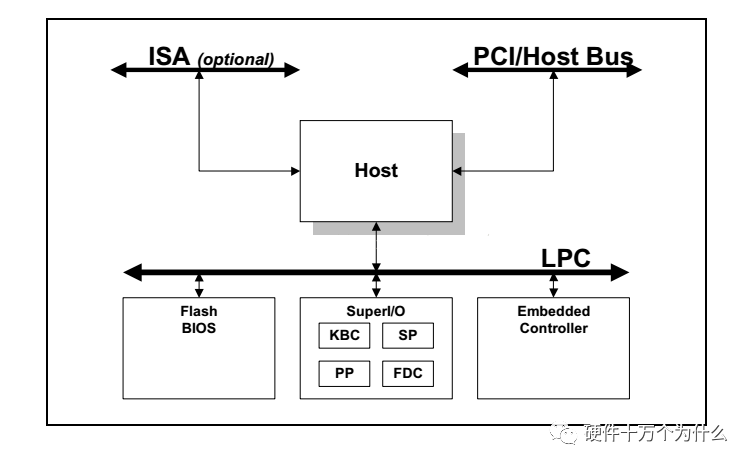
This complex hardware structure is also due to Intel’s strong shipment volume, forming its own system and standards.
Therefore, on traditional PC motherboards with an RS232 serial port, it is all implemented through Super I/O. On X86, it is also accessed through fixed addresses.
Meanwhile, the ARM architectures we are familiar with, whether Cortex-M or Cortex-A, are all MCUs or CPUs that come with serial ports—UARTs.
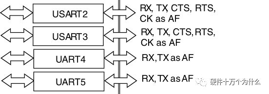
From the block diagram of the STM32F103 MCU selected by iBox, we can see a bunch of UARTs and USARTs.
However, in the design requirements of the embedded X86 system I faced at that time, there was no need for parallel ports, PS2, hardware monitoring, or FDC.
H/W Monitor: An application program reads all measurement values from hardware sensors accessed by the computer.
FDC: Provides an interface between the main processor and the floppy disk drive (floppy disk—those who understand this are revealing their age).
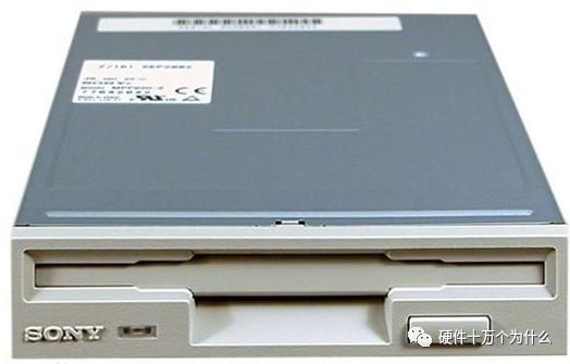
Parallel port: There are four modes: Standard Parallel Port (SPP), Bi-directional Parallel Port (BPP), Enhanced Parallel Port (EPP), and Extended Capabilities Port (ECP). The input/output mode can be controlled through DIR.

Those who recognize the above image are again revealing their age.
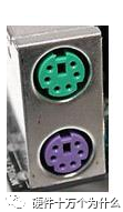
KBC: The circuit provides functions including a keyboard and a PS2 mouse. The controller receives serial data from the keyboard and mouse, checks for parity, and outputs this data to its output buffer. Some basic settings can be understood from its read/write commands.
UART: Finally, we come to the main character of this article, UART, or the serial port. In old desktop computers or laptops, there is usually a UART that conforms to the RS232 voltage standard:
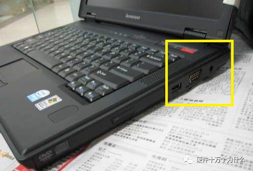
We have previously published related content about various voltage standards of serial ports:
UART, RS-232, RS-422, RS-485
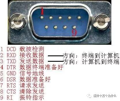
The UART output from SuperIO is generally also TTL level, which needs to be connected to an RS232 chip, and then to a DB9 interface.
The addressing space of the X86 system is somewhat complex: in addition to memory space (Memory), there is also I/O space. For detailed content, click:
Processor Series (7) – Addressing Space
The I/O space is
In X86 development, low-speed peripherals such as serial ports are accessed and read/written through I/O space:
From the UART Device Configuration Registers, we know that the base addresses of UART1~UART4 are 03F8H, 02F8H, 03E8H, and 02E8H.
GPIO: General Purpose Input/Output
ACPI: ACPI is a system for controlling computer power.
For traditional telecom embedded systems implemented by PowerPC, apart from the serial port, other functions are not needed; at the same time, some NorFlash, registers, and sensor data need to be accessed through the MPI interface, which cannot be achieved by SuperIO chips.
Additionally, due to the multifunctionality of SuperIO, its size is large, and it has many pins.
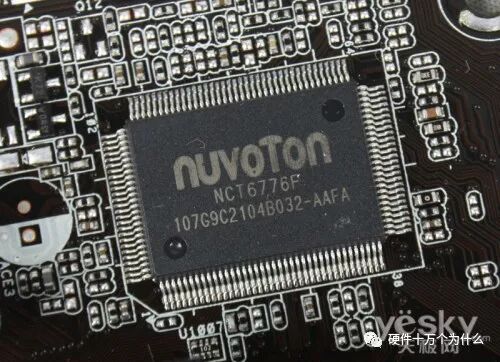
Therefore, in the design requirements at that time, using a SuperIO was not suitable. So we chose a CPLD to implement the LPC interface control for the UART interface.
Since I have worked on this, I am particularly familiar with the working process of UART. Moreover, we initially customized many registers according to our ideas, and the addresses were designed according to our preferences, resulting in commercial software like Windows and commercial Linux being unable to directly recognize the serial port. Later, we reverted to the base addresses: 03F8H, 02F8H, 03E8H, and 02E8H.
2. Working Principles of Serial Ports
1. Let’s use a phone call as an example to explain the working principle of the serial port:
When making a phone call, speaking is serial, that is, one word at a time.
The sender sends information to the receiver in a serial manner:

Since the other party hears one word at a time, each word is sent to the other party in chronological order.
If we use GPIO to transmit signals, we can only transmit “high” and “low” levels; the signal can either be “high” or “low”. Therefore, this pin can only convey two states, similar to a beacon tower, either “on” or “off”.
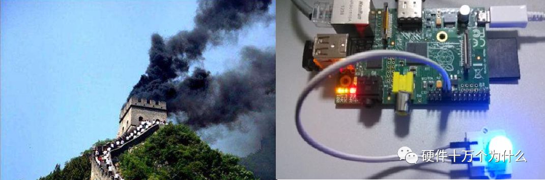
Thus, when we use GPIO to light up, we generally represent the state with two states: “on” and “off”.

However, two states cannot meet our information transmission needs. Therefore, we hope to transmit a series of “on” and “off” signals to convey more complex information, similar to the principles of telegraphs or naval signal lights.

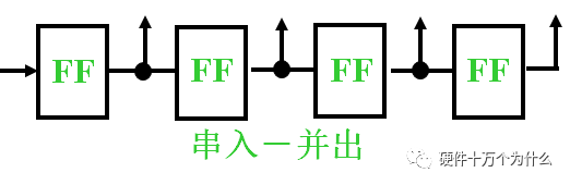
2. How to convert serial data to parallel?
Just like making a phone call, we need to listen to a complete sentence, receive all the words, then form words and sentences, and finally understand the meaning of the sentence.
Those who have studied “Digital Circuits” should remember the “shift register”, right?
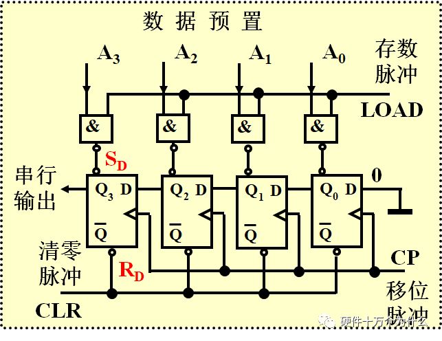
Details, I guess you have forgotten all about them, or perhaps you never learned them properly… Later in work, it seems that it was not needed. (Now in hardware, it seems that as long as the schematic PCB is correct, it is fine, without caring about circuit principles.)
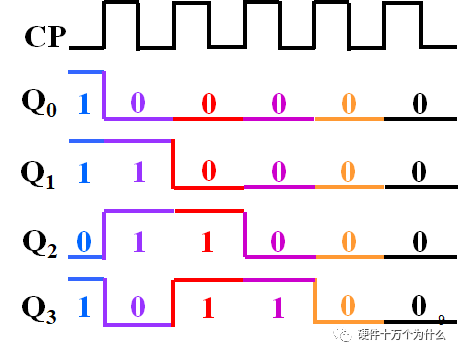
The general idea is:
Initial state: Set A3A2A1A0 = 1011
Then the output of Q3, at each clock pulse, outputs A3A2A1A0 serially in that order.
It actually utilizes the characteristics of D flip-flops.
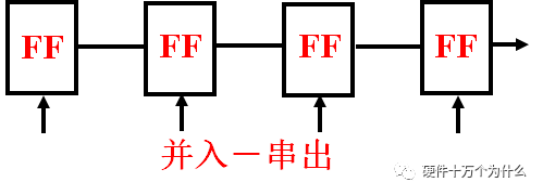
If we use an 8-bit shift register, we can utilize 8 clock cycles to send a group of 8-bit data through one wire.
The reception is the same, but the process is reversed:
3. Hello! XXXX Goodbye
When making a phone call, we usually start with “Hello!”.
This is a signal notifying the other party: “I am about to speak”.
Since we cannot see each other during a phone call, we do not know the other person’s expressions, eyes, actions, or whether they are listening to us. Therefore, we use a piece of information to notify the other party to start communication.
In the communication process of the serial port, we also need to notify the other party: I am about to communicate.
In fact, many interface principles are similar: first, there must be a normal state, and then a different state is sent to inform the other party that it has started!
For UART, there must first be a normal state—high level (as for why it is high level, there are various explanations, but personally, I think it does not matter, and reversing it does not affect anything).
So, we need to use a piece of information to tell the receiver that I am about to send data. The simplest method is to suddenly pull the level low, so that a falling edge can be detected, or a low level can be detected, and we can consider that it has started.
UART has chosen such a simple and straightforward method:
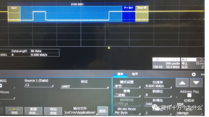
In the above image, the low level at Start is actually a signal indicating the start. We call this the start bit.
Similarly, when making a phone call, we need to say “Goodbye”.
When I call my dad, he usually does not say goodbye or similar closing remarks, often leading to: I haven’t finished speaking, and he hangs up. This forces me to redial.
This “goodbye” has an additional layer of meaning compared to the usual farewell we say when leaving, indicating: “The communication can stop now!”
Therefore, UART also needs such information to notify the other party that I have finished speaking, and you can process it now.
This is the “stop bit”, and the method is also very simple: “high level”!
As shown in the STOP in the above image.
4. Baud Rate—Speech Speed
Because the A in UART stands for asynchronous:
(Universal Asynchronous Receiver/Transmitter)
Asynchronous means that when I send you a signal, I do not send you a clock;
The receiver needs:
1. The clock error between the sender and receiver cannot be too large.
2. The clocks for analyzing data on both sides need to remain basically consistent.
For example:
If the sender sends a 9600 baud rate signal, but the receiver’s baud rate is set to 19200. The start bit is fine because it can receive that falling edge, low level. So it will parse the data, but errors will occur. We can analyze the signal:
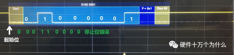
The white numbers represent the original intention sent out at 9600 baud rate: 01000001
As a result, the receiver at 19200 baud rate, which is twice that of 9600, samples at twice the rate, and the parsed data becomes: 00011000
This leads to “errors”.
This is also why, when connecting serial ports, both sending and receiving parties need to unify the “baud rate”.
3. Voltage Standards of Serial Ports
1. TTL
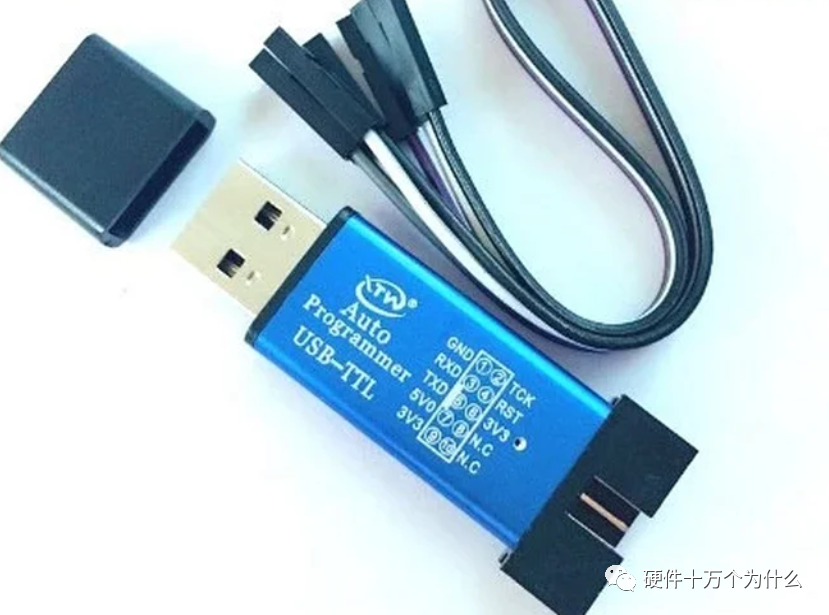
Generally, the serial port tools used for debugging directly use the TTL voltage standard UART, which is simple and cost-effective. The downside is that it cannot be transmitted over long distances.
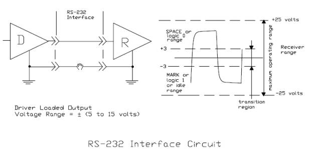
2. RS-232 Standard
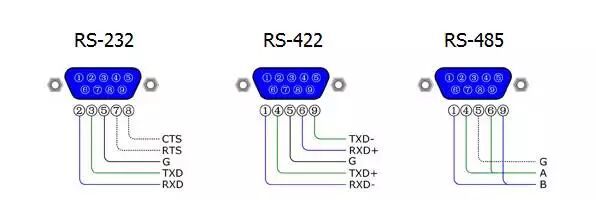
RS-232 is a serial physical interface standard established by the Electronic Industry Association (EIA) in the United States. RS stands for “Recommended Standard”, and 232 is the identification number. RS-232 specifies electrical and physical characteristics and only applies to the data transmission path; it does not include data processing methods. It should be noted that many people often mistakenly refer to RS-232, RS-422, and RS-485 as communication protocols, which is incorrect; they are merely mechanical and electrical interface standards for UART communication (at most, they pertain to the physical layer of network protocols).
The standard specifies the use of a 25-pin DB-25 connector, detailing the signal content for each pin, and also specifies the voltage levels for various signals. Later, IBM simplified RS-232 to a DB-9 connector, which has become the de facto standard today. The RS-232 port used in industrial control generally only uses RXD (2), TXD (3), and GND (5) lines.
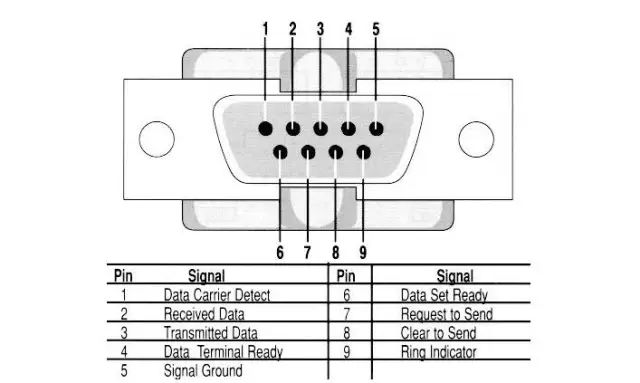 Since early PCs all came with RS-232 interfaces, we needed to use UART, so we chose RS-232. However, now personal computers, including laptops and desktops, no longer have RS-232 interfaces; we see that there are no DB9 interfaces on computer motherboards. Therefore, development boards now choose TTL UART or directly implement UART to USB on the development board.
In embedded systems, the term serial port generally refers to the UART port, but we often confuse it with the COM port, as well as the relationships between RS232, TTL, etc. In fact, UART and COM refer to the physical interface form (hardware), while TTL and RS-232 refer to the voltage standards (electrical signals).
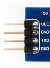
UART has 4 pins (VCC, GND, RX, TX), using TTL levels, where low level is 0 (0V) and high level is 1 (3.3V or above).
3. RS-485/RS-422 Standards
The RS-232 interface can achieve point-to-point communication, but this method cannot realize networking. Therefore, to solve this problem, a new standard, RS-485, was developed. The data signal of RS-485 uses differential transmission, also known as balanced transmission, using a pair of twisted wires, defining one wire as A and the other as B.
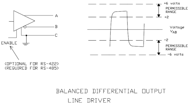
Typically, the positive voltage between the sending driver A and B is +2 to +6V, representing one logic state, while the negative voltage is -2 to +6V, representing another logic state. There is also a signal ground C, and RS-485 has an “enable” terminal, which is optional in RS-422.
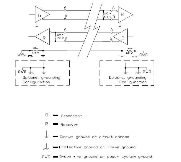
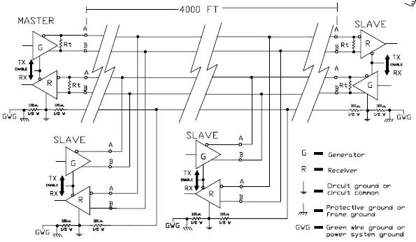
RS-422 has the same electrical performance as RS-485. The main difference is that RS-422 has 4 signal lines: two for sending and two for receiving. Since RS-422 separates receiving and sending, it can receive and send simultaneously (full duplex), and because full duplex requires separate channels for receiving and sending, RS-422 is suitable for communication between two stations, star networks, and ring networks, but not for bus networks; RS-485 only has 2 signal lines, so it can only operate in half-duplex mode, commonly used in bus networks.
1. The electrical characteristics of RS-485: Logic “1” is represented by the voltage difference between the two wires being + (2~6)V; Logic “0” is represented by the voltage difference being – (2~6)V. The signal voltage levels of RS-232-C are higher, making it easier to damage the interface circuit chips, and since the 232 levels are not compatible with TTL levels, a level conversion circuit is required to connect with TTL circuits.
2. The maximum data transmission rate of RS-485 is 10Mbps.
3. The RS-485 interface uses a combination of balanced drivers and differential receivers, enhancing its ability to resist common-mode interference, meaning it has good noise immunity.
4. The maximum communication distance of RS-485 is about 1219M, with a maximum transmission rate of 10Mb/S. The transmission rate is inversely proportional to the transmission distance; at a transmission rate of 100Kb/S, the maximum communication distance can be achieved. If longer distances are needed, RS-485 repeaters must be added. The RS-485 bus generally supports a maximum of 32 nodes, and if special RS-485 chips are used, it can reach 128 or 256 nodes, with a maximum of 400 nodes.
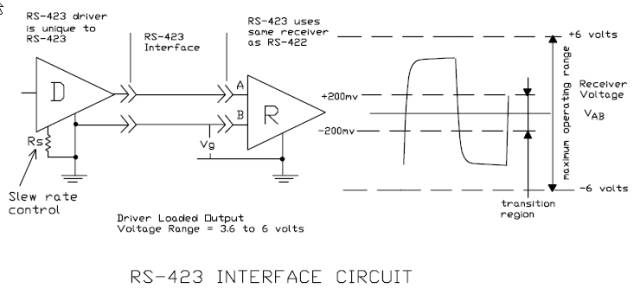
RS-423 is an unbalanced serial communication interface.
Structure, signal levels, transmission distance, transmission rate, interface chips.
RS-422 is a balanced serial communication interface.
Structure, signal levels, interface chips, MC3486, MC3487, SN75154, SN75155.
Transmission rate, transmission distance.
RS-485 serial communication bus
Structure, signal levels, interface chips MAX485.
Transmission rate, transmission distance, application examples.
Due to the early emergence of the RS-232 interface standard, it inevitably has some shortcomings, mainly four points:
(1) The signal voltage levels of the interface are relatively high, making it easy to damage interface circuit chips, and because the 232 levels are not compatible with TTL levels, a level conversion circuit is required to connect with TTL circuits;
(2) The transmission rate is relatively low; in asynchronous transmission, the baud rate is 20Kbps. Now, due to the use of new UART chips, the baud rate has reached 115.2Kbps (1.832M/16);
(3) The interface uses one signal line and one signal return line to form a common ground transmission form, which is prone to common-mode interference, making it weak against noise interference;
(4) The transmission distance is limited; the maximum transmission distance standard value is 50 meters, but in practice, it can only be used at around 15 meters;
(5) RS-232 only allows one-to-one communication and does not consider forming a serial bus. (This point is very important; in many control scenarios, it is one control to many. If the master device needs to communicate point-to-point with the slave devices, the wiring on-site will become a spider web.)
Unbalanced serial communication interfaces RS-423, RS-449
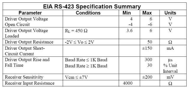
Balanced serial communication interface RS-422
RS-422 (EIA RS-422-A Standard) is the serial port connection standard for Apple’s Macintosh computers. RS-422 uses differential signals, while RS-232 uses unbalanced reference ground signals. Differential transmission uses two wires to send and receive signals, which, compared to RS-232, provides better noise immunity and longer transmission distances. In industrial environments, better noise immunity and longer transmission distances are significant advantages.
4. Comparison between RS-232 and RS-485
1. Anti-interference: The RS485 interface uses a combination of balanced drivers and differential receivers, providing good noise immunity. The RS232 interface uses one signal line and one signal return line to form a common ground transmission form, which is prone to common-mode interference.
2. Transmission distance: The maximum transmission distance standard for RS485 is 1200 meters (at 9600bps), but it can actually reach 3000 meters. RS232 has a limited transmission distance, with a maximum standard value of 50 meters, but in practice, it can only be used at around 15 meters.
3. Communication capability: The RS-485 interface allows up to 128 transceivers on the bus, enabling users to easily establish a device network using a single RS-485 interface. RS-232 only allows one-to-one communication.
4. Transmission rate: RS-232 has a lower transmission rate, with a baud rate of 20Kbps in asynchronous transmission. RS-485 has a maximum data transmission rate of 10Mbps.
5. Signal lines: The RS485 interface forms a half-duplex network, generally requiring only two signal lines. The RS-232 port generally uses RXD, TXD, and GND lines.
6. Electrical voltage levels: The logic “1” of RS-485 is represented by the voltage difference between the two wires being + (2-6)V; logic “0” is represented by the voltage difference being – (2-6)V. In RS-232-C, the voltage of any signal line is in a negative logic relationship. That is, logic “1” is -5 to -15V; logic “0” is +5 to +15V.
5. Comparison between RS-422 and RS-485
The electrical performance of RS-485 is identical to that of RS-422. The main differences are:
1. RS-422 has 4 signal lines: two for sending (Y, Z) and two for receiving (A, B). Since RS-422 separates receiving and sending, it can receive and send simultaneously (full duplex).
2. RS-485 only has two data lines: sending and receiving are both A and B. Since RS-485 shares the two lines for receiving and sending, it cannot receive and send simultaneously (half duplex).
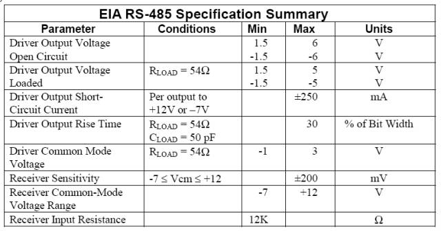
The RS-485 standard uses balanced transmission and differential reception data transceivers to drive the bus, with specific specifications:
The input resistance of the receiver RIN ≥ 12kΩ
The driver can output a common-mode voltage of ±7V
The input capacitance ≤ 50pF
With 32 nodes and 120Ω termination resistors configured, the driver can still output a voltage of at least 1.5V (the size of the termination resistor is related to the parameters of the twisted pair used).
The input sensitivity of the receiver is 200mV (i.e., (V+) – (V-) ≥ 0.2V indicates signal “0”; (V+) – (V-) ≤ -0.2V indicates signal “1”).
Due to the long-distance, multi-node (32 nodes), and low transmission line costs of RS-485, the EIA RS-485 has become the preferred standard for data transmission in industrial applications.
(1) The electrical characteristics of RS-485: The sending end: logic “0” is represented by the voltage difference between the two wires being + (2~6)V; logic “1” is represented by the voltage difference being – (2~6)V. The receiving end: A is considered logic “0” if it is more than 200mV higher than B, and A is considered logic “1” if it is more than 200mV lower than B.
(2) The maximum data transmission rate of RS-485 is 10Mbps. However, since RS-485 often needs to communicate with the RS-232 port of a PC, the actual maximum is generally 115.2Kbps. Also, since higher rates reduce the transmission distance of RS-485, it is often around or below 9600bps.
(3) The RS-485 interface uses a combination of balanced drivers and differential receivers, providing good noise immunity.
(4) The maximum transmission distance of the RS-485 interface is 1200 meters (at 9600bps), but it can actually reach 3000 meters. The RS-485 interface allows up to 128 transceivers on the bus, meaning RS-485 has multi-machine communication capabilities, allowing users to easily establish a network using a single RS-485 interface. Since the RS-485 interface forms a half-duplex network, it generally requires only two signal lines, so RS-485 interfaces use twisted pair transmission. The international standard for RS-485 does not specify a connector standard, so terminal blocks or DB-9, DB-25 connectors can be used.
When using the RS-485 interface, the maximum cable length allowed for data signal transmission from the generator to the load is a function of the data signal rate, which is mainly limited by signal distortion and noise. The maximum cable length and signal rate relationship curve is obtained using 24AWG copper twisted telephone cable (diameter 0.51mm), with inter-wire bypass capacitance of 52.5PF/M and terminal load resistance of 100 ohms (cited from GB11014-89 Appendix A). When the data signal rate drops below 90Kbit/S, assuming the maximum allowable signal loss is 6dBV, the cable length is limited to 1200m. In practice, it is entirely possible to achieve greater cable lengths.
When using different wire gauges, the maximum cable length achieved will vary. For example, when the data signal rate is 600Kbit/S, using 24AWG cable, the maximum cable length is 200m; if using 19AWG cable (diameter 0.91mm), the cable length can exceed 200m; if using 28AWG cable (diameter 0.32mm), the cable length can only be less than 200m.
For long-distance communication with RS-485, it is recommended to use shielded cables and connect the shield layer as the ground.
6. Three Factors Affecting RS-485 Bus Communication Speed and Reliability
Signal Reflection in Communication Cables
During communication, two signal factors cause signal reflection: impedance discontinuity and impedance mismatch.
Impedance discontinuity occurs when the signal suddenly encounters a very low or no impedance at the end of the transmission line, causing reflection at that point, as shown in the figure. This principle of signal reflection is similar to light reflecting when it enters another medium. To eliminate this reflection, a termination resistor matching the characteristic impedance of the cable must be connected at the end of the cable to ensure impedance continuity. Since signals on the cable are bidirectional, a termination resistor of the same size can also be connected at the other end of the communication cable.
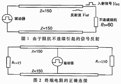
Theoretically, as long as a termination resistor matching the characteristic impedance of the cable is connected at the end of the transmission cable, signal reflection should not occur. However, in practical applications, due to the characteristic impedance of the transmission cable being related to the communication baud rate and other application environments, the characteristic impedance cannot be completely equal to the termination resistor, so some signal reflection will still exist.
Another cause of signal reflection is the impedance mismatch between the data transceiver and the transmission cable. This type of reflection mainly manifests when the communication line is idle, causing data chaos across the entire network.
The impact of signal reflection on data transmission ultimately arises because the reflected signal triggers the comparator at the receiver’s input, causing the receiver to receive incorrect signals, leading to CRC errors or entire data frame errors.
In signal analysis, the parameter used to measure the strength of the reflected signal is RAF (Reflection Attenuation Factor). Its calculation formula is as follows:
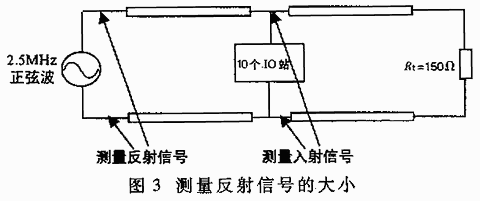
RAF=20lg(Vref/Vinc) (1)
Where: Vref—voltage magnitude of the reflected signal; Vinc—voltage magnitude of the incident signal at the connection point between the cable and the transceiver or termination resistor.
The specific measurement method is shown in Figure 3. For example, if the peak-to-peak value of a 2.5MHz incident signal sine wave is +5V, and the peak-to-peak value of the reflected signal is +0.297V, then the reflection attenuation factor of this communication cable at a 2.5MHz communication rate is:
RAF=20lg(0.297/2.5)=-24.52dB
To reduce the impact of reflected signals on communication lines, noise suppression and adding bias resistors are commonly used methods. In practical applications, for relatively small reflected signals, the method of adding bias resistors is often used for simplicity and convenience. The principle of how to improve communication reliability by adding bias resistors in communication lines.
Signal Attenuation in Communication Cables
The second factor affecting signal transmission is signal attenuation during transmission through the cable. A transmission cable can be viewed as an equivalent circuit composed of distributed capacitance, distributed inductance, and resistance, as shown in the figure.
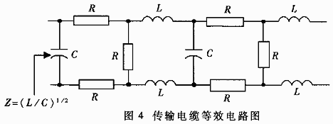
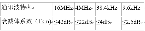
The distributed capacitance C of the cable is mainly generated by the two parallel conductors of the twisted pair. The resistance of the conductors has a minimal effect on the signal and can be ignored. The signal loss is mainly due to the LC low-pass filter formed by the distributed capacitance and distributed inductance of the cable. The attenuation coefficients of the LAN standard two-core cables used in PROFIBUS (the standard cable selected by Siemens for the DP bus) at different baud rates are shown in Table 1.
Attenuation coefficients of cables
Pure Resistive Load in Communication Cables
The third factor affecting communication performance is the size of the pure resistive load (also called DC load). Here, the pure resistive load mainly consists of termination resistors, bias resistors, and RS-485 transceivers.
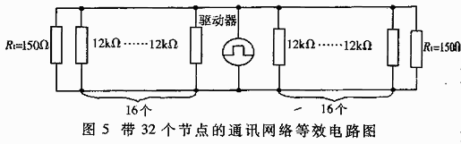
When discussing the EIA RS-485 specification, it was mentioned that the RS-485 driver can output at least 1.5V differential voltage with 32 nodes and 150Ω termination resistors configured. The input resistance of a receiver is 12kΩ, and the entire network’s equivalent circuit is shown in Figure 5. Based on this calculation, the load capacity of the RS-485 driver is:
RL=32 input resistors in parallel with 2 termination resistors=(((12000/32)×(150/2))/((12000/32)+(150/2)))≈51.7Ω
Currently, commonly used RS-485 drivers include MAX485, DS3695, MAX1488/1489, and SN75176A/D used by Holley, among others, some of which can achieve a load capacity of 20Ω. Without considering many other factors, based on the driving capacity and load relationship, a driver can support a maximum number of nodes far exceeding 32.
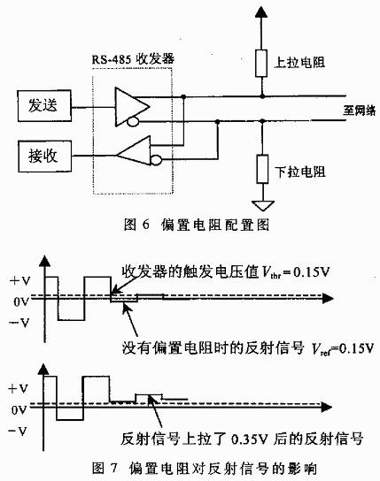
When the communication baud rate is relatively high, bias resistors are necessary on the line. The connection method for bias resistors is shown in Figure 6. Their role is to pull the level away from 0V when there is no data on the bus (idle state), as shown in Figure 7. This way, even if small reflected signals or interference occur in the line, the data receivers connected to the bus will not malfunction due to these signals.
Through the following example, we can calculate the size of the bias resistor:
Termination resistors Rt1=Rr2=120Ω;
Assuming the maximum peak-to-peak value of the reflected signal Vref≤0.3Vp-p, then the negative half-cycle voltage Vref≤0.15V; the reflected current Iref caused by the reflected signal on the termination resistor ≤0.15/(120||120)=2.5mA. The hysteresis voltage value of a typical RS-485 transceiver (including SN75176) is 50mV, that is:
(Ibias-Iref)×(Rt1||Rt2)≥50mV
Thus, we can calculate that the bias current Ibias≥3.33mA
+5V=Ibias(Rup+Rdown+(Rt1||Rt2)) (2)
Using equation (2), we can calculate Rup=Rdown=720Ω
In practical applications, there are two methods for adding bias resistors to the RS-485 bus:
(1) Distributing the bias resistors evenly to each transceiver on the bus. This method adds bias resistors to each transceiver connected to the RS-485 bus, providing each transceiver with a bias voltage.
(2) Using a pair of bias resistors on a segment of the bus. This method is effective for large reflected signals or interference signals on the bus. It is worth noting that adding bias resistors increases the load on the bus.
7. The Relationship Between the Load Capacity of the RS-485 Bus and the Length of Communication Cables
When designing the network configuration of the RS-485 bus (bus length and number of loads), three parameters should be considered: pure resistive load, signal attenuation, and noise margin. The pure resistive load and signal attenuation have been discussed earlier; now we will discuss noise margin. The noise margin of the RS-485 bus receiver should be at least greater than 200mV. The previous discussions assumed a noise margin of 0. In practical applications, to improve the bus’s anti-interference capability, it is always hoped that the system’s noise margin is better than that specified in the EIA RS-485 standard. The relationship between the number of loads on the bus and the length of communication cables can be seen from the following formula:
Vend=0.8(Vdriver-Vloss-Vnoise-Vbias)(3)
Where: Vend is the signal voltage at the end of the bus, which is specified as 0.2V during standard measurement; Vdriver is the output voltage of the driver (related to the number of loads. For 5 to 35 loads, Vdriver=2.4V; when the number of loads is less than 5, Vdriver=2.5V; when the number of loads exceeds 35, Vdriver≤2.3V); Vloss is the signal loss during transmission in the bus (related to the specifications and length of the communication cable), calculated based on the attenuation coefficient provided in Table 1, using the formula attenuation coefficient b=20lg(Vout/Vin), we can calculate Vloss=Vin-Vout=0.6V (note: the communication baud rate is 9.6kbps, and the cable length is 1km; if the baud rate increases, Vloss will also increase); Vnoise is the noise margin, which is specified as 0.1V during standard measurement; Vbias is the bias voltage provided by the bias resistors (typical value is 0.4V).
In equation (3), multiplying by 0.8 is to prevent the communication cable from entering a fully loaded state. From equation (3), it can be seen that the size of Vdriver is inversely proportional to the number of loads on the bus, and the size of Vloss is inversely proportional to the length of the bus; the other parameters are only related to the type of driver used. Therefore, once the driver for the RS-485 bus is selected, the number of loads on the bus is directly related to the maximum distance the signal can be transmitted at a fixed communication baud rate. The specific relationship is: within the allowable range of the bus, the more loads there are, the shorter the distance the signal can be transmitted; the fewer loads there are, the longer the distance the signal can be transmitted.
8. The Impact of Distributed Capacitance on RS-485 Bus Transmission Performance
The distributed capacitance of the cable is mainly generated by the two parallel conductors of the twisted pair. Additionally, there is also distributed capacitance between the conductors and ground, which, although small, cannot be ignored in analysis. The impact of distributed capacitance on bus transmission performance mainly arises because the transmitted signal on the bus is a fundamental wave signal, and the signal is expressed only as “1” and “0”. In special bytes, for example, 0x01, the signal “0” allows sufficient charging time for the distributed capacitance, while when the signal “1” arrives, the charge in the distributed capacitance cannot discharge in time, resulting in (Vin+) – (Vin-) still being greater than 200mV, causing the receiver to mistakenly interpret it as “0”, ultimately leading to CRC check errors and incorrect transmission of the entire data frame. The specific process is shown in the figure.

Due to the influence of distribution on the bus, data transmission errors occur, leading to a decrease in overall network performance. To solve this problem, two methods can be employed:
(1) Reduce the data transmission baud rate;
(2) Use cables with low distributed capacitance to improve the quality of the transmission line.
Simply connecting the A and B ends of each interface with a pair of twisted wires without grounding the signals of the RS-485 communication link can work in some cases, but it poses risks to the system. The RS-485 interface transmits signals differentially and does not require a reference point to detect the signal system; it only needs to detect the potential difference between the two wires. However, it should be noted that the transceiver can only operate normally when the common-mode voltage does not exceed a certain range (-7V to +12V). When the common-mode voltage exceeds this range, it can affect communication reliability and even damage the interface. As shown in Figure 1, when transmitter A sends data to receiver B, the common-mode voltage at transmitter A’s output is VOS. Due to the existence of ground potential differences VGPD between the two systems, the common-mode voltage at the receiver’s input can reach VCM=VOS+VGPD. The RS-485 standard specifies that VOS≤3V, but VGPD can vary significantly (dozens of volts or even higher), and may be accompanied by strong interference signals, causing the common-mode input VCM to exceed the normal range, generating interference currents on the signal line that affect normal communication or damage the equipment.
4. Transmission Distance of Serial Cables
The serial interface (Serial Interface) refers to the sequential transmission of data one bit at a time. Its characteristics include a simple communication line, requiring only a pair of transmission lines to achieve bidirectional communication (telephone lines can be directly used as transmission lines), significantly reducing costs, especially suitable for long-distance communication, but with slower transmission speeds. The transmission of each bit of information is done sequentially, and serial communication can range from a few meters to several kilometers; based on the direction of information transmission, serial communication can be further divided into simplex, half-duplex, and full-duplex.
In summary:
The two most basic methods of serial communication are synchronous serial communication and asynchronous serial communication.
Synchronous serial refers to SPI (Serial Peripheral Interface), which is a synchronous serial peripheral interface. The SPI bus system allows MCUs to communicate with various peripheral devices in a serial manner to exchange information; TRM450 is an SPI interface.
Asynchronous serial refers to UART (Universal Asynchronous Receiver/Transmitter), which is a chip that converts parallel input into serial output, usually integrated on the motherboard. UART includes TTL level serial ports and RS232 level serial ports. TTL level is 3.3V, while RS232 is negative logic level, defining +5~+12V as low level and -12~-5V as high level; MDS2710, MDS SD4, EL805 are RS232 interfaces, while EL806 has a TTL interface.
Serial interfaces are categorized by electrical standards and protocols, including RS-232-C, RS-422, RS-485, etc. The RS-232-C, RS-422, and RS-485 standards only specify the electrical characteristics of the interfaces and do not involve connectors, cables, or protocols.
RS-232:
Also known as the standard serial port, it is the most commonly used serial communication interface. It was established in the 1970s by the Electronic Industry Association (EIA) in collaboration with Bell Systems, modem manufacturers, and computer terminal manufacturers as a standard for serial communication. Its full name is “Serial Binary Data Exchange Interface Standard between Data Terminal Equipment (DTE) and Data Communication Equipment (DCE).” The traditional RS-232-C interface standard has 22 wires, using a standard 25-pin D-type plug socket (DB25), which was later simplified to a 9-pin D-type socket (DB9), and the 25-pin plug socket is rarely used in current applications.
RS-232 adopts an unbalanced transmission method, known as single-ended communication. Since the voltage difference between the sending and receiving levels is only about 2V to 3V, its common-mode rejection capability is poor, and combined with the distributed capacitance on the twisted pair, its maximum transmission distance is about 15 meters, with a maximum speed of 20kb/s. RS-232 is designed for point-to-point communication (i.e., only one pair of receiving and sending devices), with a driver load of 3 to 7kΩ. Therefore, RS-232 is suitable for communication between local devices.
pt; background:rgb(255,255,255); mso-shading:rgb(255,255,255); ” >, RS485, etc. The RS-232-C, RS-422, and RS-485 standards only specify the electrical characteristics of the interfaces and do not involve connectors, cables, or protocols.
RS-422
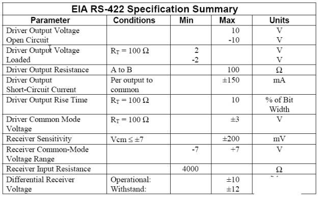
The full standard is “Electrical Characteristics of Balanced Voltage Digital Interface Circuits,” which defines the characteristics of the interface circuit. A typical RS-422 is a four-wire interface. In fact, there is also a signal ground wire, making a total of five wires. Its DB9 connector pin definitions. Since the receiver adopts high input impedance and the sending driver has stronger driving capability than RS232, it allows multiple receiving nodes to be connected on the same transmission line, with a maximum of 10 nodes. That is, one master device (Master) and the rest as slave devices (Slave), and slave devices cannot communicate with each other, so RS-422 supports bidirectional communication from one to many. The input impedance of the receiver is 4k, so the maximum load capacity of the sender is 10×4k+100Ω (termination resistance). The maximum transmission distance of RS-422 is 1219 meters, with a maximum transmission rate of 10Mb/s. The length of the balanced twisted pair is inversely proportional to the transmission rate; the maximum transmission distance can only be achieved at rates below 100kb/s. Only at very short distances can the highest transmission rate be achieved. The maximum transmission rate on a 100-meter long twisted pair is only 1Mb/s.
RS-485
RS-485 is developed based on RS-422, so many electrical specifications of RS-485 are similar to those of RS-422. Both use balanced transmission methods and require termination resistors on the transmission line. RS-485 can use two-wire and four-wire methods; the two-wire system can achieve true multi-point bidirectional communication, while the four-wire connection, like RS-422, can only achieve point-to-many communication, meaning there can only be one master device and the rest as slave devices. However, it has improved, allowing up to 32 devices to be connected on the bus, regardless of whether it is a four-wire or two-wire connection.
Another difference between RS-485 and RS-422 is that their common-mode output voltages are different; RS-485 is between -7V and +12V, while RS-422 is between -7V and +7V. The minimum input impedance of RS-485 receivers is 12kΩ, while for RS-422, it is 4kΩ. Since RS-485 meets all RS-422 specifications, RS-485 drivers can be used in RS-422 networks.
Like RS-422, RS-485 has a maximum transmission distance of about 1219 meters and a maximum transmission rate of 10Mb/s. The length of the balanced twisted pair is inversely proportional to the transmission rate; the maximum transmission distance can only be achieved at rates below 100kb/s. Only at very short distances can the highest transmission rate be achieved. The maximum transmission rate on a 100-meter long twisted pair is only 1Mb/s.