Now let’s get into today’s main topic (the author is using the battleship STM32 library function version): today I will discuss two knowledge points with you: 1. Analysis of the RTC clock block diagram (important) 2. How time is displayed (brief analysis)
1. Analysis of the RTC Clock Block Diagram (Important)
First, let’s familiarize ourselves with several key points:
1. The real-time clock (RTC) of STM32 is an independent timer!
2. The RTC module and clock configuration system (RCC_BDCR register) are in the backup area, meaning that after the system reset wakes from standby mode, the RTC settings and time remain unchanged.
In this section about RTC, the operations related to RTC registers are particularly important, and I won’t explain them here; please refer to the manual yourself.
First, here’s the diagram!
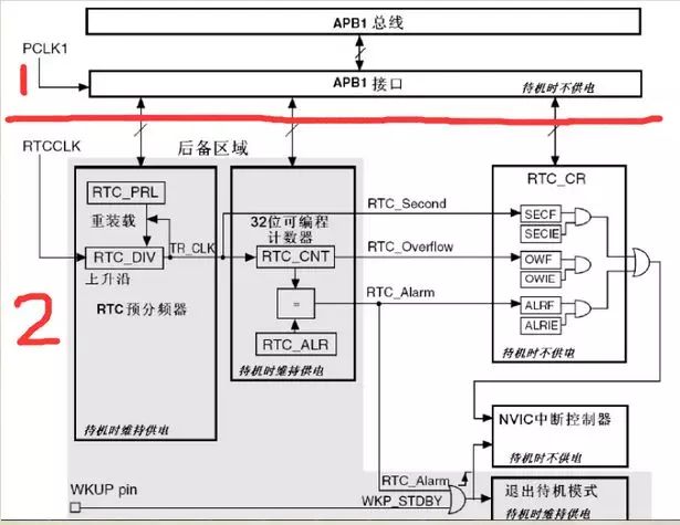
RTC Clock Block Diagram
The RTC clock block diagram consists of two completely independent parts: 1. APB1 interface part (for RTC-related registers); 2. RTC core;
First part: APB1 interface. Note: Here we refer to the RSF bit in the RTC_CRL register, which is the synchronization flag of the register. Please refer to the STM32 reference manual, chapter on RTC for specifics.
Second part: RTC core. This part is divided into two modules: 1. RTC prescaler module; 2. A 32-bit programmable counter;
Next, let’s analyze the second part:
First, let me introduce several particularly important registers in the backup area:
1. RTC_DIV (Important): RTC prescaler remainder register. The purpose of this register is to obtain a clock more accurate than a second (0.1s, 0.01s). This register is self-decrementing and is used to store how many clock cycles are needed to obtain a second signal. Here’s a formula (available in the STM32 reference manual): fTR_CLK=fRTCCLK/(PRL[19:0]+1) – this is the exact wording from the book!
To explain, the value of the RTC_DIV register is provided by the RTC_PRL (RTC prescaler load register), and the clock frequency of the RTC_DIV register is provided by RTCCLK (see the diagram). For example, if we set the RTC_PRL value to 32767, then the value of the RTC_DIV register will also be 32767, matching the clock frequency of RTCCLK (based on the above formula, RTC_PRL plus 1 means RTC_DIV also plus 1). The clock period of RTCCLK is 1/32768(s), meaning that for each clock cycle of RTCCLK, RTC_DIV decrements by 1 until after 1 second, it is reloaded by hardware, which means it decrements 32768 times to get to 1 second. But how does it provide 0.1s or even 0.01s?
Let’s clarify with an example. If I want to obtain 1.12 seconds, RTC_DIV is required to decrement 0.12/(1/32768) times. RTC_DIV only accounts for 0.12s; where does the remaining 1s come from? It is provided by TR_CLK. This issue will be explained in detail later.
2. RTC_PRL: RTC prescaler load register. This register has two functions: 1. Provides the reload value for RTC_DIV; 2. Sets the clock division factor.
The first function will not be discussed here. The second function: setting the clock division factor. For example, if we use a 32.768KHz crystal oscillator as the clock input, then we configure this register value to 32767, we can obtain a 1-second counting frequency (32768/(32767+1), unit (HZ)).
3. RTC_CNT (Important): RTC counter register. This register is relatively simple and is used to record the second value. If the related interrupt enable bits for RTC_CR (control register) are configured, the RTC_CNT register can generate an overflow interrupt.
4. RTC_ALR: RTC alarm register. As can be seen from the diagram, it is very simple. It is used to mark the time when the alarm is generated. If the value of RTC_CNT equals the value of RTC_ALR and the interrupt is enabled (configured in RTC_CR), an alarm interrupt will be generated.
That’s all for introducing the registers in the backup area. Based on the introduction above combined with the block diagram, you should have a rough process in mind, right? No? Oh no! Let me clarify the thought process for you.
First, an external clock signal RTCCLK (32.768K) is input, and then the RTC_PRL division factor is set to 32767 to obtain a second clock signal TR_CLK (1HZ). When TR_CLK passes one clock cycle, it generates an RTC_Second (second interrupt), while the RTC_CNT counter (which records the second value) increments by 1. If more precise time is required, the value of RTC_DIV can be read when the RSF bit in the RTC_CR register is set to 1.
2. How is time displayed? (Brief Analysis)
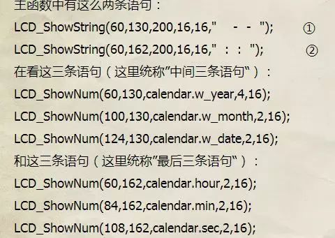
Clearly, the three statements in the middle correspond to displaying the year, month, and day ①, while the last three statements correspond to displaying hours, minutes, and seconds ②. All these structure members are assigned values in the initialization function (RTC_Init();). How they are assigned is for you to research on your own… Then in the hardware, every clock cycle of TR_CLK will trigger the second interrupt, and in the second interrupt service function, the time is updated.
To display time, we must first set a base time and then allow the system to increment from that base time.
Step 1: Set a base time. When configuring the clock (in the initialization function (RTC_Init();), there is a function RTC_Set(); which calculates the total number of seconds from 1970 to the time you set, and assigns this calculated second value to the RTC_CNT counter as the initial value.
Step 2: The system updates the time itself (increments). How is time updated? Here’s a brief mention.. In the update function (RTC_Get();), it first reads the value in the RTC_CNT counter, then calculates the year, month, day, hours, minutes, seconds, and week, assigning values to those time structure variables. Thus, in the main function’s while(1), the time is continuously refreshed by the second interrupt and displayed on the LCD.
In this way, a complete clock is displayed on the LCD screen. Mission accomplished!
Author: Houqi