This article begins by introducing microcontrollers from the perspective of integrated circuits, mainly covering the pin diagram and functions of microcontrollers, as well as basic programming.
First, let’s take a look at the functional block diagram of the 80C51 microcontroller.
The 80C51 microcontroller belongs to the MCS-51 series and uses a 40-pin dual in-line package (DIP), containing 128 RAM units and 4K ROM.
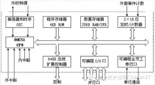
Functional Structure Diagram of the 80C51 Microcontroller
Next, we will introduce the pin diagram and functions of the microcontroller (as shown in the figure below). The specific functions of the pins will be detailed later.
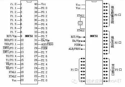
The 40 pins of the microcontroller can be roughly divided into four categories: power, clock, control, and I/O pins.
1. Power:
⑴ VCC – Chip power supply, connect to +5V;
⑵ VSS – Ground terminal;
2. Clock:
XTAL1, XTAL2 – Inverting input and output terminals of the crystal oscillator circuit.
3. Control Lines:
There are a total of four control lines:
⑴ ALE/PROG: Address latch enable / internal EPROM programming pulse
① ALE function: Used to latch the lower 8 bits of the address sent by port P0.
② PROG function: For chips with internal EPROM, this pin inputs programming pulses during EPROM programming.
⑵ PSEN: External ROM read enable signal.
⑶ RST/VPD: Reset / backup power.
① RST (Reset) function: Reset signal input terminal.
② VPD function: Connects to backup power in case of Vcc power failure.
⑷ EA/Vpp: Internal/external ROM selection / internal EPROM programming power.
① EA function: Internal/external ROM selection terminal.
② Vpp function: For chips with internal EPROM, applies the programming power Vpp during EPROM programming.
4. I/O Lines:
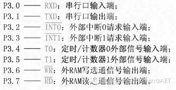
The 80C51 has four 8-bit parallel I/O ports: P0, P1, P2, and P3, totaling 32 pins. Port P3 also has a second function for special signal input/output and control signals (part of the control bus).
When you get a chip, the first thing you need to know is how to connect it. We will use a chip called 89C51. Let’s see how to connect it.
1. Power supply: This is essential. The microcontroller uses a 5V power supply, with the positive connected to pin 40 and the negative (ground) connected to pin 20.
2. Oscillator circuit: The microcontroller is a timing circuit and must be supplied with pulse signals to function normally. An oscillator is integrated within the microcontroller, using a crystal oscillator connected to pins 18 and 19. Just buy a crystal oscillator and capacitors, connect them according to figure 1, and you’re good to go.
3. Reset pin: Connect as shown in figure 1. As for what reset means and why it is needed, this will be explained in the microcontroller functions section.
4. EA pin: The EA pin connects to the positive power supply. At this point, the microcontroller is connected, and once powered, it starts working.
Our first task is to use the microcontroller to light up an LED. Clearly, this LED must be connected to one of the microcontroller’s pins; otherwise, the microcontroller cannot control it. So, which pin should we connect it to? Besides the five pins we just used, there are still 35 left. We will connect this LED to pin 1 (see figure 1, where R1 is the current-limiting resistor).
According to this connection diagram, when pin 1 is high, the LED does not light up; it only lights up when pin 1 is low. Therefore, we need to control pin 1, which means we need to be able to change pin 1 to high or low as required. Since we want to control pin 1, we need to give it a name; we can’t just call it pin 1, right? What should we call it? The company that designed the 51 chip, INTEL, has already named it P1.0; this is a standard and cannot be changed by us.
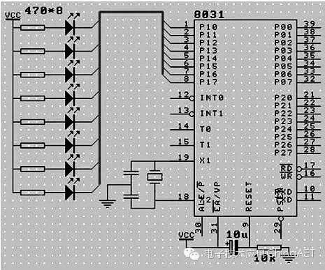
Figure 1 Simple Application Circuit of the Microcontroller
Simple Programming of the Microcontroller
Now that we have a name, how do we make it go ‘high’ or ‘low’? To command someone to do something, you simply give an order; to make a computer do something, you also need to issue commands. The commands that a computer can understand are called instructions. To output a high level on a pin, the instruction is SETB, and to output a low level, the instruction is CLR. Thus, to make P1.0 output a high level, just write SETB P1.0; to make P1.0 output a low level, simply write CLR P1.0.
Now we have a way to make the computer output high or low levels on P1.0, but how can we get the computer to execute this instruction? We can’t just say it and expect it to work, right? To solve this problem, there are a few steps to take.
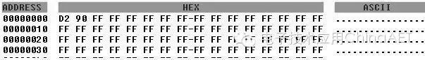
First, the computer does not understand instructions like SETB or CLR; we need to translate the instruction into a format the computer can understand. What does the computer understand? It only understands one thing—numbers. Therefore, we need to convert SETB P1.0 into (D2H, 90H) and CLR P1.0 into (C2H, 90H). As for why these are the two numbers, this is also defined by the designers of the 51 chip—INTEL, and we won’t delve into that.
The second step, after obtaining these two numbers, is to get them into the microcontroller. This requires a hardware tool called a “programmer.” If you don’t know what a programmer is, let me introduce it: it’s a tool that allows you to write the code you create on your computer into the microcontroller’s EPROM using an assembler or compiler. Programming the 80C51 type microcontroller is quite tedious; it must first be programmed on a programmer before it can be used in a device. However, the latest AT89s51 or STC89C51 microcontrollers support in-system programming (ISP), which allows you to write code into the microcontroller without removing it, using simple circuitry.
We connect the programmer to the computer, run the programmer software, and then write (D2H, 90H) in the editing area (see figure 2), write it in… Good, take the chip out, insert it into the prepared circuit board, power it on… What? The light is not on? That’s correct because the instruction we wrote is to make P1.0 output a high level, so the light will not be on. If it were on, that would be wrong. Now we take this chip out, put it back on the programmer, and change the content in the editing area to (C2H, 90H), which is CLR P1.0, write the chip, take it out, insert it into the circuit board, power it on, and good, the light is on. Because the instruction we wrote is to make P1.0 output a low level. Thus, we see that without changing any hardware connections, we can change the output effect of the circuit simply by changing the content written into the microcontroller.