
What is a map file?
In simple terms, a map file is a mapping file that combines programs, data, and IO space after compilation by the compiler.
Many highly skilled engineers first think of analyzing the map file when encountering memory overflow or out-of-bounds situations. The map file provides important information such as function sizes and entry addresses.
Program Size: Code=1112 RO-data=320 RW-data=0 ZI-data=1632
About Map Files in Keil
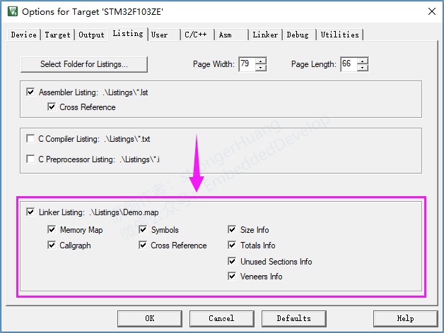
Main configurations include:
-
Memory Map: Memory Mapping
-
Callgraph: Call Graph
-
Symbols: Symbols
-
Cross Reference: Cross References
-
Size Info: Size Information
-
Totals Info: Total Information
-
Unused Section Info: Unused Module Information
-
Veneers Info: Veneer Information
Note:
A. By default, all information is outputted
The following chapters will provide detailed explanations of the five categories of content generated by the map files of Keil MDK and ARM Compiler 5 components.
Descriptions of Each Module
1. Section Cross References: Module and Section (Entry) Cross References
Check in configuration: Cross Reference
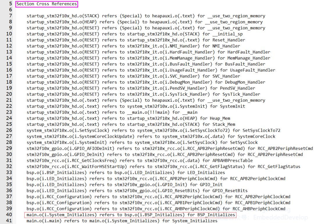
Section Cross References: Module and Section (Entry) Cross References refer to the relationship of mutual references between modules and sections generated by each source file.
main.o(i.System_Initializes) refers to bsp.o(i.BSP_Initializes) for BSP_Initializes
The System_Initializes function (i.System_Initializes) in the main module (main.o) calls the BSP_Initializes function in the bsp module (bsp.o).
B. I.System_Initializes is the entry of the System_Initializes function
2. Removing Unused input sections from the image: Removing Unused Modules
Check in configuration: Unused Sections Info
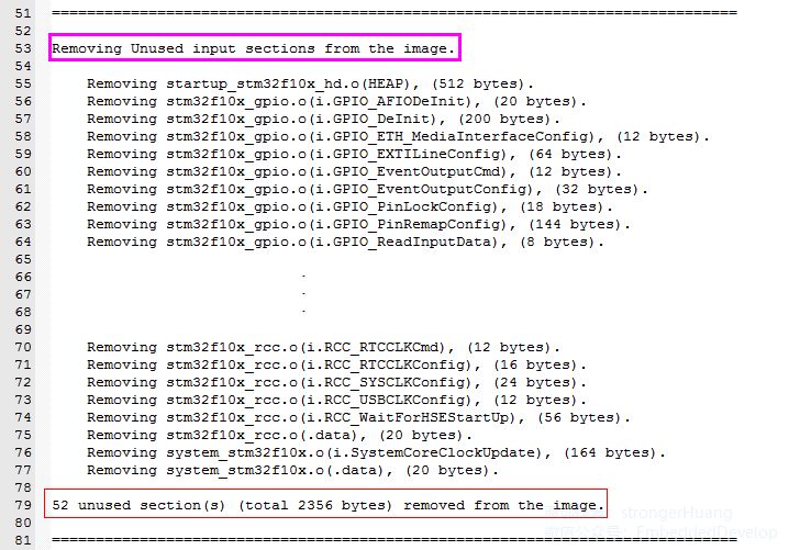
This category is easy to understand; it generates a list in the map file of modules (or functions) in our code that have not been called.
For example:
Removing stm32f10x_gpio.o(i.GPIO_AFIODeInit), (20 bytes).
The GPIO_AFIODeInit module (function) in the stm32f10x_gpio.c file has not been called, with a code size of 20 bytes.
52 unused section(s) (total 2356 bytes) removed from the image.
(2) The total size of unused sections is 2356 bytes;
3. Image Symbol Table: Mapping Symbol Table
Check in configuration: Symbols
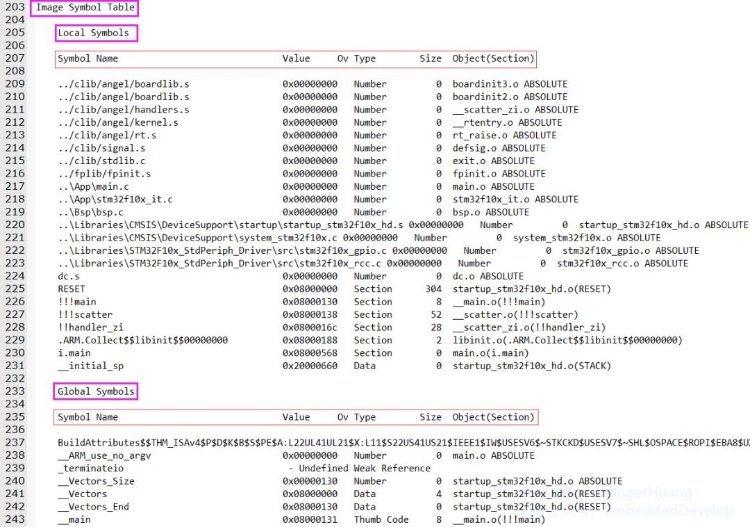
Image Symbol Table: Mapping Symbol Table refers to the table storing the corresponding addresses of each section (the image has removed some middle content).
-
Local Symbols: Local -
Global Symbols: Global
Key Points of Symbol Content
For naming and classification, please refer to the official reference document provided at the end.
0x2000xxxx refers to variables and Data stored in RAM.
Careful readers will notice: global, static variables, etc., are located in the 0x2000xxxx memory RAM.
This is easy to understand; it refers to the size occupied by the current line Symbol.
This generally refers to the module (source file) in which it is located.
4. Memory Map of the image: Memory (Mapping) Distribution
Check in configuration: Memory Map

Memory Map of the image: Memory (Mapping) Distribution is relatively extensive and an important item.
Main Introduction:
Image Entry point : 0x08000131: refers to the mapping entry address.
Load Region LR_IROM1 (Base: 0x08000000, Size: 0x00000598, Max: 0x00080000, ABSOLUTE):
Indicates that the loading area is at the starting address of LR_IROM1, 0x08000000, with a size of 0x00000598, and this area has a maximum size of 0x00080000.
B. Execution Region RW_IRAM1
This area corresponds to the regions in our target configuration, as shown in the figure below:
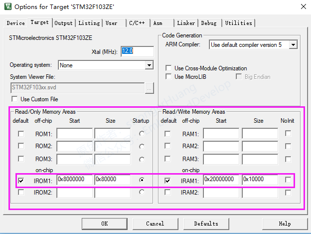
Key Points of Content:
0x0800xxxx FLASH address and 0x2000xxxx RAM address.
(2) Size: Storage Size
The ARM processor is 32-bit; if an 8-bit or 16-bit variable is defined, some portion will remain, which refers to the “padding” part, and you will find that the other options behind it do not have corresponding values.
RW: Stored with segments in RAM
It generally includes: RESET, .ARM, .text, i, .data, .bss, HEAP, STACK, etc.
(6) Object: Target
5. Image component sizes: Storage Component Sizes
Check in configuration: Size Info
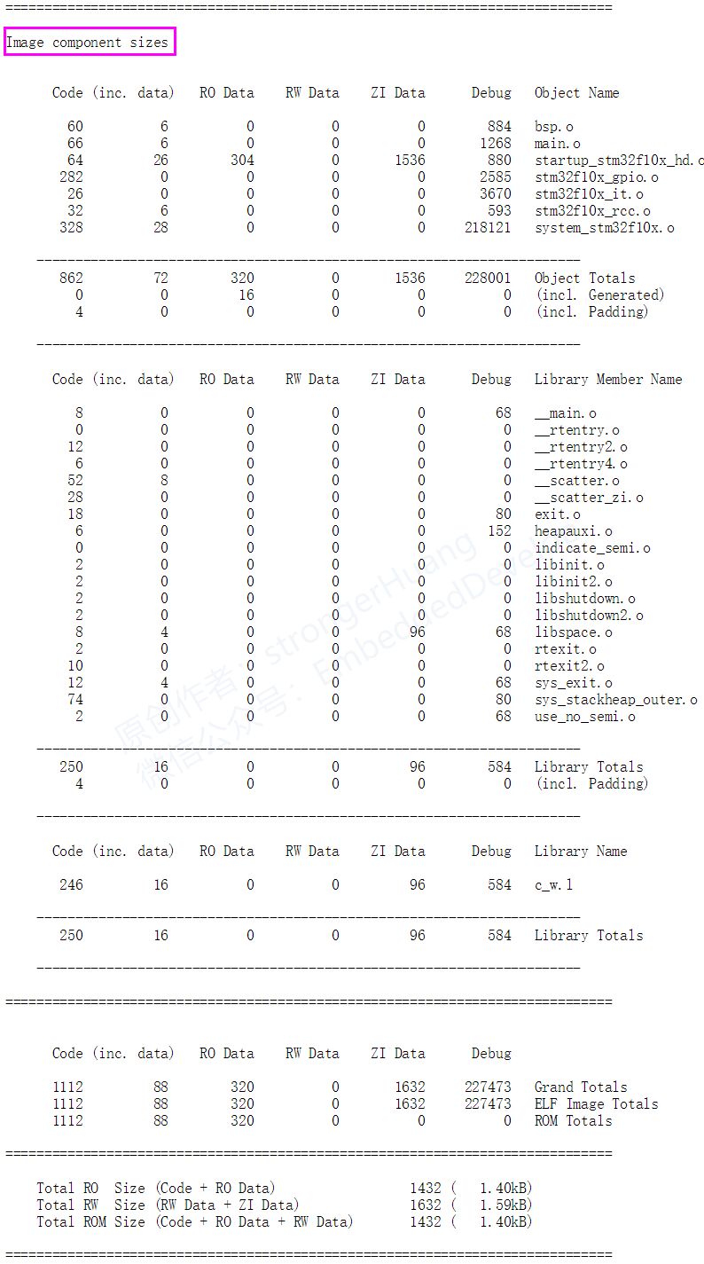
Image component sizes: Storage Component Sizes mainly summarizes the storage size information of modules.
Program Size: Code=1112 RO-data=320 RW-data=0 ZI-data=1632
ZI-data: refers to uninitialized (ZI) variable data;
C. RW-data initialized data will be stored in Flash, and upon power-up, it will be moved from FLASH to RAM.
ROM Size = Code + RO Data + RW Data
The above map information is a comprehensive summary; if you do not want to look at detailed information about those modules, you can only check “Totals Info” in the configuration to compare the information:
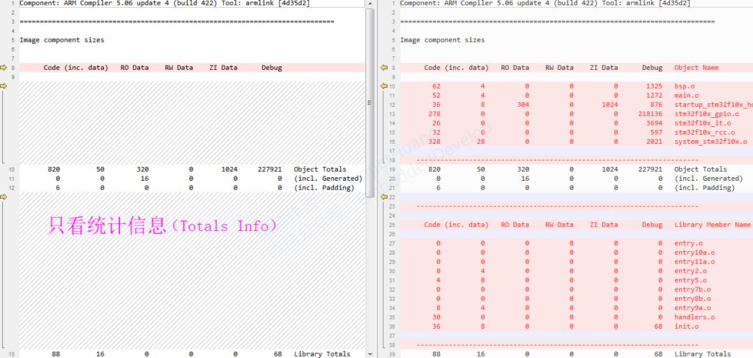

END