The LCDs we purchase generally consist of two parts:
The LCD panel and the LCD driver chip
Our processor does not directly drive the LCD panel, but rather drives the LCD driver chip, which in turn drives each pixel on the LCD panel.
Therefore, to make the LCD display certain content, we need to consider two points:
What communication bus and protocol the processor uses to communicate with the control chip, and what data format is used to transmit display data to the control chip, as well as the bus form used to communicate with the control chip.
Some LCDs use parallel bus communication, while others use serial bus communication.
For parallel bus communication, we need to consider:
When the data on the bus is latched, how to distinguish between command data and display data, and whether there are multiple control chip select signals.
For serial bus communication, we need to consider:
Whether to use SPI or I2C bus, and the communication rate and other parameters.
In short, we need to know how the processor communicates to ensure that the LCD’s control chip receives the data.
Transmission format of display data
Each LCD’s control chip has an internal RAM, where each data bit in the RAM corresponds to the respective pixel on the LCD. For example, the internal RAM of a 128*32 LCD control chip is a 128*32 bit RAM. If a bit in the RAM is 0, the corresponding pixel on the LCD does not display; if it is 1, it will display.
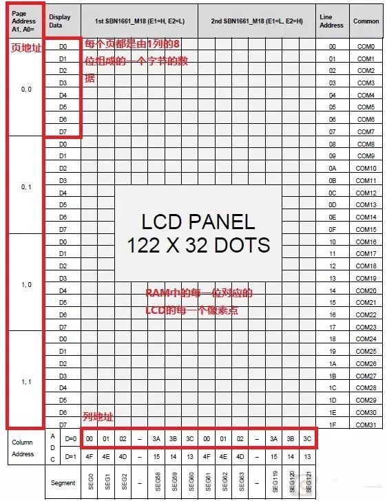
The above image shows the address mapping of the RAM of a 122*32 dot matrix LCD control chip (the LCD in the image uses two control chips, so its column addresses range from two 0-60). The RAM indicates the position of a pixel in a manner similar to rows and columns, but in RAM, the row corresponds to the page address, and the column corresponds to the column address. Typically, in RAM, eight adjacent bits in a column form one byte. For instance, the RAM for a 128*32 bit array is represented as LCD_RAM_DATA[4][128]. The adjacent eight bits in a column are referred to as one page, as shown in the page address of the above image. This means that in the above array, LCD_RAM_DATA[0][*] corresponds to the data where the page address is 0, and LCD_RAM_DATA[2][*] corresponds to the data where the page address is 2. The column address is straightforward; for example, LCD_RAM_DATA[1][10] corresponds to the eight pixels with a page address of 1 and a column address of 10.
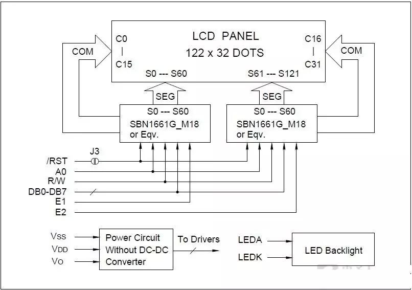
Different LCDs use different control chips, and the number varies. To understand how the LCD’s control chip is connected, one must refer to the LCD’s manual. Some screens use a single control chip to drive the LCD, while others use multiple control chips. The following images illustrate the block diagrams for LCDs using one control chip and two control chips, respectively.
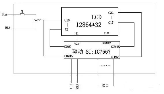

An LCD using a single control chip corresponds to the entire LCD in its RAM content.
Using multiple control chips divides the screen into several parts, with each control chip corresponding to a specific area. For example, two driver ICs divide the screen into left and right halves. Therefore, modifying such an LCD requires adjusting the corresponding control chip’s RAM based on the pixel’s location. When communicating with an LCD that has multiple control chips, one must also consider the chip select signals for different control chips to manage data acquisition. Fundamentally, the principle of using multiple control chips is similar to that of using a single control chip, except that one RAM is divided among multiple control chips’ RAMs.
Summary
Ultimately, the image presented on the LCD is the data in the RAM. To display different content on the LCD, one must modify the RAM of each control chip. Therefore, the primary operations revolve around manipulating the RAM. For instance, setting the page address and column address for RAM writing or reading, as well as writing to or reading from the specified RAM address.