
Summer is here, and it’s the buzzing season for mosquitoes, which is no different in China or abroad.
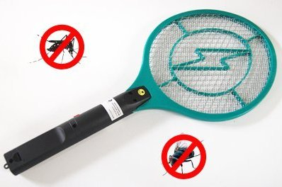
Today we introduce a project that upgrades our weapon—the electric mosquito swatter—to make our battle with mosquitoes a bit more fun!
The upgraded electric mosquito swatter features include:
-
Add an electronic device to detect lethality -
Add a 4-digit counter to tally “kills” -
Support USB charging -
Add a “kill sound” for a better experience
▼ Click to see the effect
Creative Concept
The author’s idea is that when a mosquito hits the metal mesh of the electric swatter and creates an arc, there must be some change in current in the circuit of the swatter. If we can find a point in the circuit that can be read by Arduino or ATtiny (i.e., between 0 to 5 volts), then it’s easy to count and display scores and play sounds.
The sound function can be easily added to ATtiny using the DFPlayer module.
The score will be displayed using a 4-digit 7-segment display, which can be driven by the onboard TM1637 with just two wires (two IO pins of ATtiny).
Since these electronic modules operate at 5V, while the electric mosquito swatter typically uses two 1.5V batteries, we can also upgrade the power supply of the swatter using a USB rechargeable battery.
In other words, this “weapon upgrade” is made using relatively easy-to-find off-the-shelf electronic modules, with the only complex part being the signal calculation, which is handled by ATtiny through programming.
In the tutorial shared below, it is assumed that everyone has some understanding of Arduino and how to program; if not, you can first learn the basics of Arduino tutorials.
Before we start, a safety issue needs to be mentioned:
The electric mosquito swatter uses high voltage (with several hundred volts on the mesh when the button is pressed). Even though the current is very low, be careful not to touch it or its internal circuit when connecting the batteries.
Do not let children play with this.
Materials
For this “ultimate” electric mosquito swatter, we need:
-
An electric mosquito swatter -
Digispark pro (with ATtiny, easily found online) -
DFPlayer (available from DFRobot) -
Resistors: 1Ω, 1kΩ -
8Ω speaker -
SD card (a small capacity card to store some sound files) -
Lithium-ion rechargeable battery: used battery -
Battery charger -
Potentiometer (I used a 1MΩ, which is not very important, but a high value will limit the current consumption through the potentiometer) -
4-digit LED display with TM1637 (make sure it is a 4-digit display + TM1637, not just a 4-digit display) -
Capacitor: 470μF -
On/Off toggle switch -
Button -
Wires (reuse old phone or network cables)
For tools, we need a soldering iron, a hot glue gun, and a 3D printer (some creativity to modify the handle of the swatter…)
Step 1: How to Upgrade Our Electric Mosquito Swatter?
If you don’t care how it works and just want to make the “ultimate” electric mosquito swatter, you can skip this step.
Resources explaining how the electric mosquito swatter works can be found online.
<span>https://www.homemade-circuits.com/mosquito-swatter-bat-circuit/</span>
It consists of an oscillating circuit and a circuit that boosts the voltage to several hundred volts, plus the metal mesh connected to the swatter.
The first problem encountered is that nothing can be hung on the ATtiny here (due to the 5V limitation of the ATtiny, the high-voltage side cannot be used directly).
To solve this problem, the second idea is to measure current consumption.
When an arc occurs on the metal mesh, and the mosquito is electrocuted, there must be some energy consumption that should be readable by the ATtiny.
The best way to measure this consumption is to measure the voltage across a resistor, which the ATtiny can do.
Therefore, the method of counting mosquitoes is to insert a small resistor between the battery and the electric mosquito swatter circuit and monitor the voltage across this resistor.
In addition, we use ready-made electronic modules (each function has one: sound, display, charger, etc.), so overall, this is a relatively simple electronic project.
Step 2: Prepare the Circuit
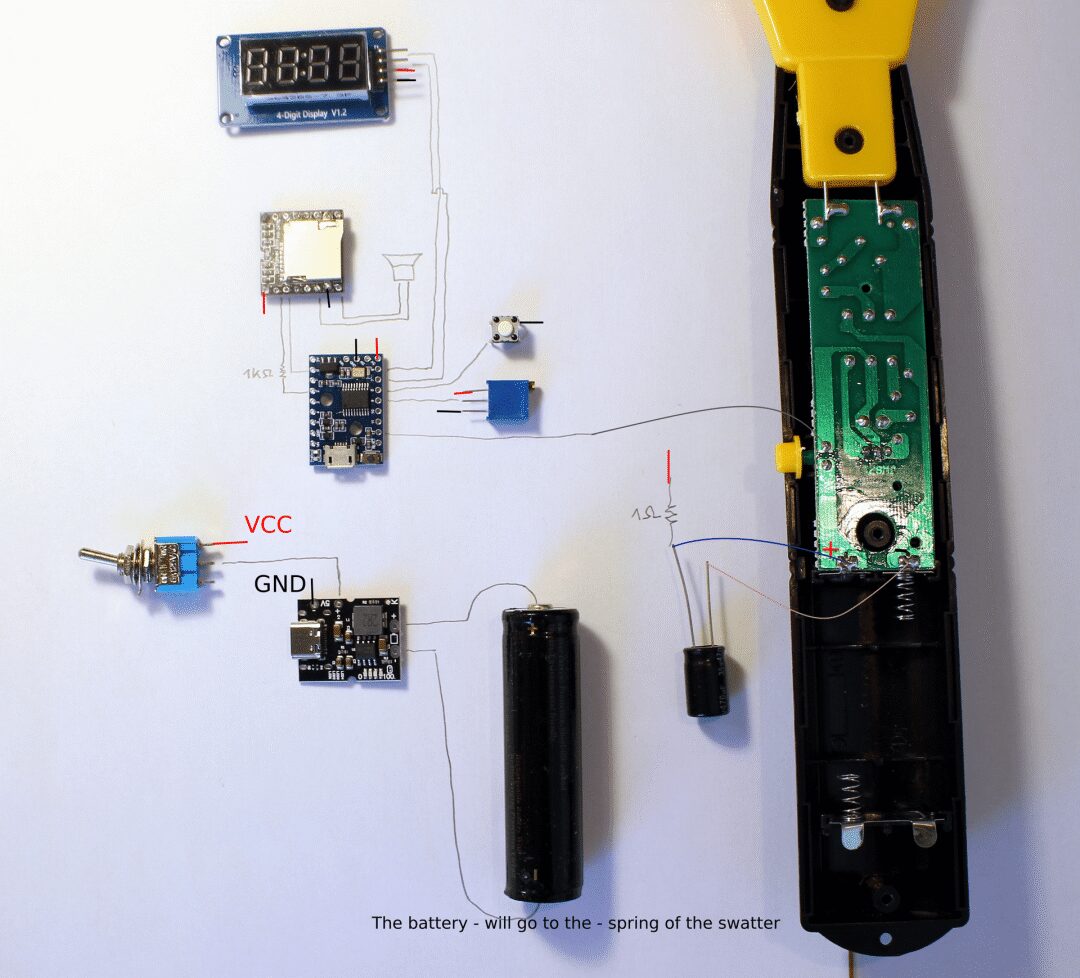
The main components are:
-
ATtiny (Digispark pro) -
DFPlayer -
USB charger and battery -
Display -
Reset button -
On/Off switch -
Potentiometer for volume adjustment -
Two resistors and one capacitor
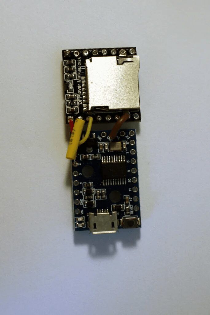
We should first arrange them to ensure they fit inside the handle; Digispark and DFPlayer can be placed closer together, leaving appropriate wire lengths for other components (i.e., the USB charger has a USB port that needs to be used for charging).
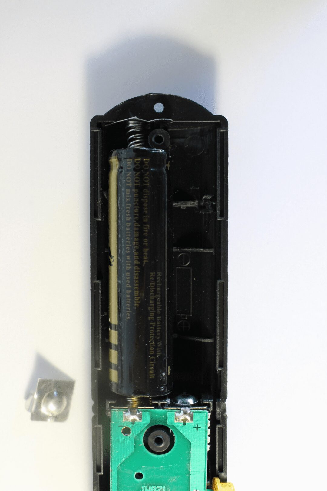
Step 3: Disassemble the Electric Mosquito Swatter
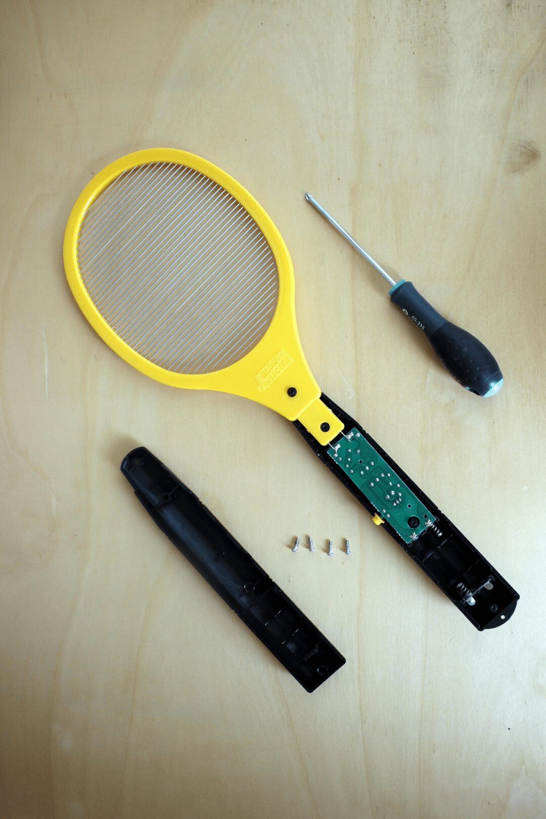
Remove the battery and disassemble the swatter (there should be only a few screws).
Take a look at how much space we have for additional components.
Also, check if your swatter is the same as the one used in this tutorial.
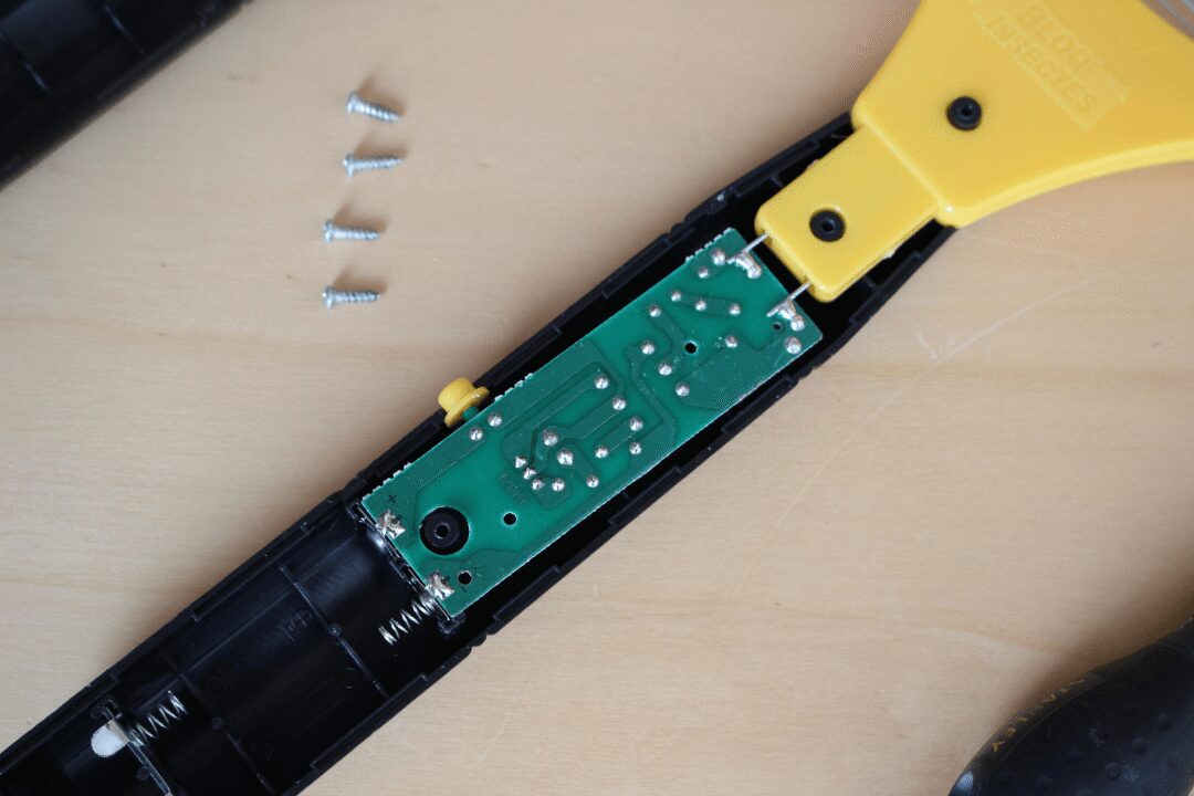
The main difference to note is the “position” of the swatter’s push button. In the picture, it is located between the battery’s<span>+</span> and the circuit of the swatter. If so, you’re good (see photo).
On some swatters, this button is between the ground<span>-</span> and the circuit. In this case, the modifications and code below will not work. Adjustments will need to be made in both hardware and software.
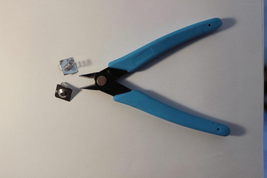
Step 4: Modify the Electric Mosquito Swatter
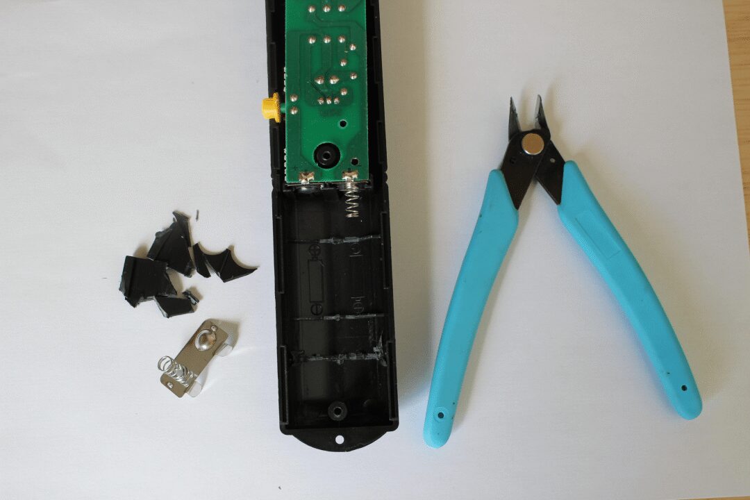
In this step, we:
-
Clear some space for the batteries designed for two AAA batteries (and reuse the battery connector from the rechargeable battery).
Step 5: Build the Circuit and Solder Components
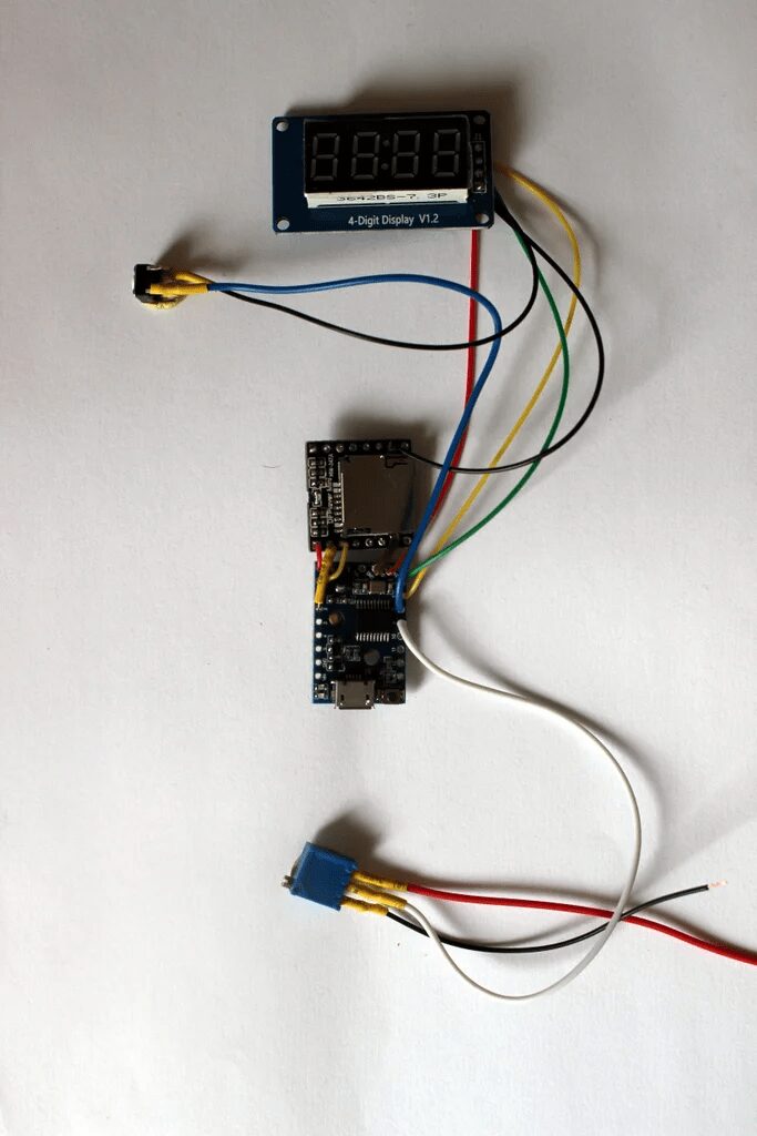
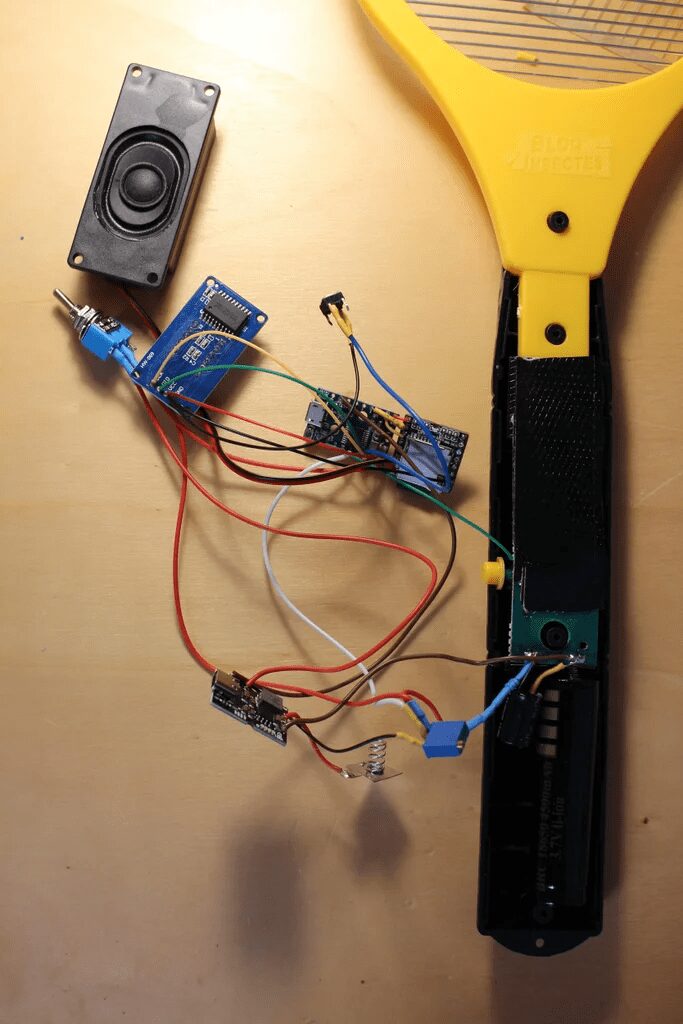
Layout the final positions of all components, estimate the lengths of various wires, and start soldering.
In the previous step, ground and VCC (5V) lines were not drawn for clarity, but all ground lines need to be connected to each other, and all VCC lines need to be connected to each other.
For VCC, the Digispark has three pins marked 5V, which are interconnected and can be redistributed to other components. Do not use the VIN of the Digispark (VIN requires a voltage input higher than 6V, we do not use it, but use the 5V output from the battery charger).
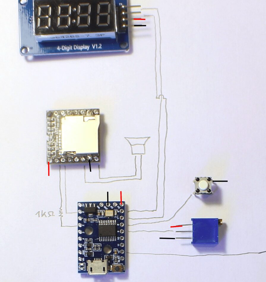
It is recommended to start with Digispark:
-
Solder Digispark to DFPlayer -
Solder Digispark to the display, button, and potentiometer -
Use heat shrink tubing to avoid contact and short circuits (e.g., on the resistor between Digispark and DFPlayer)
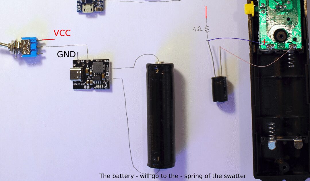
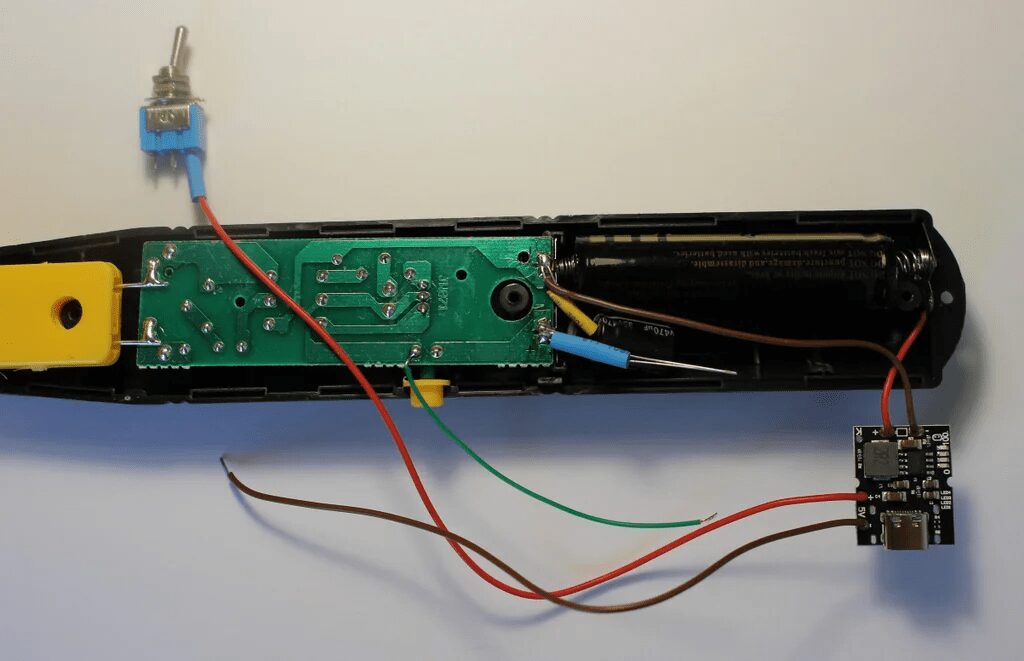
Then, continue connecting the electric mosquito swatter circuit, battery charger, and switch:
-
Battery <span>-</span>to charger Battery<span>-</span>Input -
Battery <span>+</span>to charger Battery<span>+</span>Input -
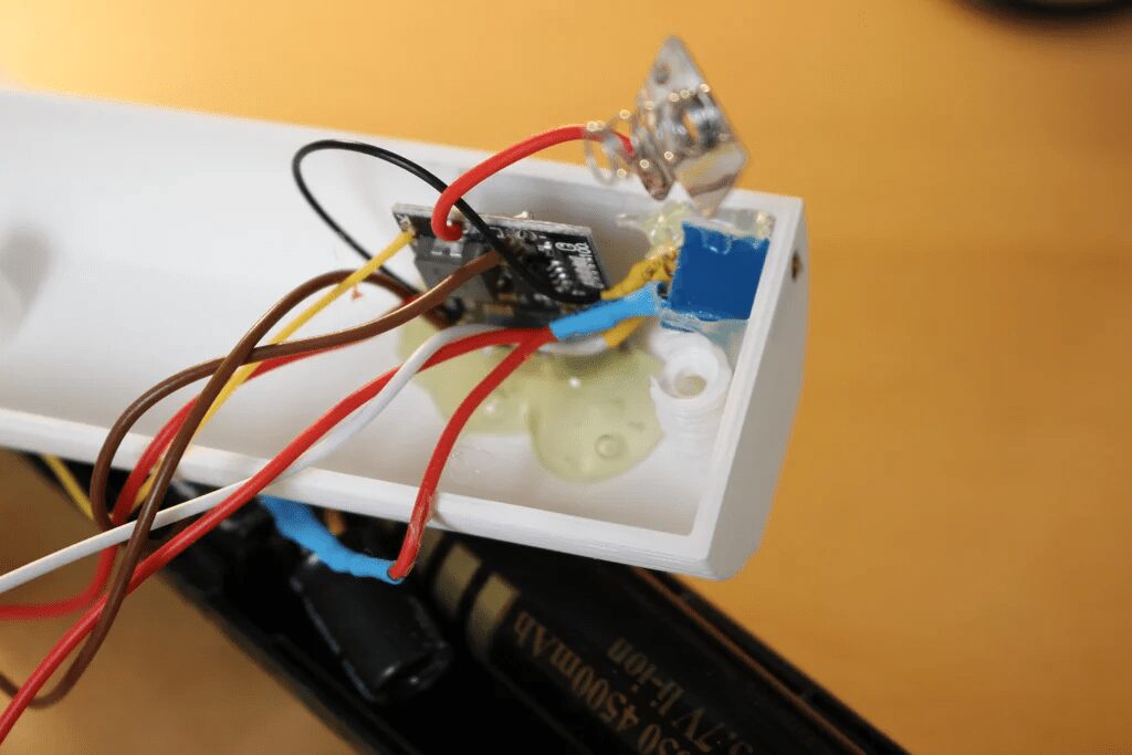
1-ohm resistor on the electric mosquito swatter circuit <span>+</span> -
Capacitor on the electric mosquito swatter circuit’s <span>+</span>and<span>-</span>terminals, noting the polarity of the capacitor! -
Digispark’s A12 pin connected to the button (the button has two terminals, one connected to the battery <span>+</span>and A12 connected to the other) -
Use heat shrink tubing to avoid contact and short circuits (on the capacitor/resistor, etc.).
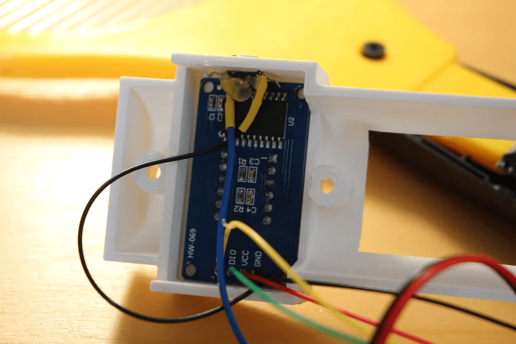
Step 6: Isolate the Display from the Electric Mosquito Swatter Circuit
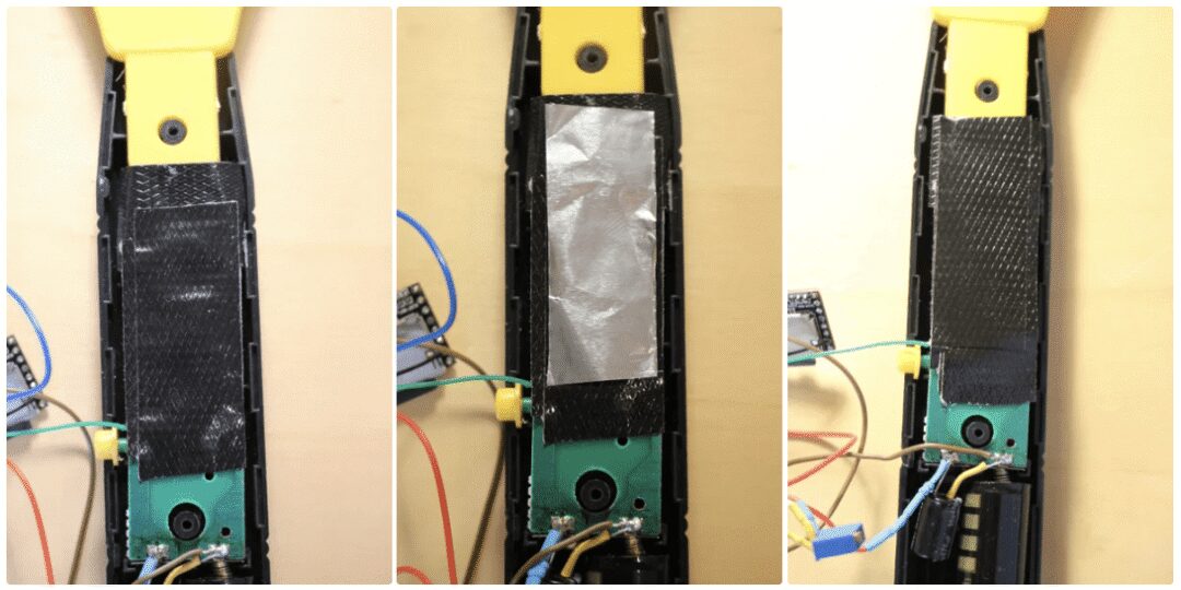
During testing, display issues were encountered—when a mosquito hits the mesh of the electric mosquito swatter, the display will turn off or malfunction.
It is suspected that the changes in high voltage are causing electromagnetic interference affecting the display circuit and connections.
The fix is simple: place some tape or aluminum foil (electromagnetic shielding) on the circuit, then tape over it.
Of course, do not place aluminum foil directly on the circuit…
Step 7: Load Sounds onto the SD Card
The sounds played by the DFPlayer are stored on the SD card.
The procedure is simple: insert the card and then copy the selected sounds:
-
Sound played on power-up (“Ready for the next battle”) -
A sound for “Monster Killed” -
A sound for “Level Up” -
Some randomly played sound files when a kill is detected
The DFPlayer will play sounds based on “track number”.
It has been observed that the files are not sorted by their names, but by their<span>inode</span> numbers on the card (which can be viewed in Linux using <span>ls -id</span>).
ls -id * | more
647 1_Monster_kill.mp3
648 2_mixkit-final-level-bonus-2061.wav
649 3_get_ready_to_the_newt_fight.mp3
650 mixkit-arcade-retro-scoring-counter-273.wav
651 mixkit-arcade-video-game-bonus-2044.wav
652 mixkit-arcade-video-game-scoring-presentation-274.wav
653 mixkit-game-bonus-reached-2065.wav
654 mixkit-game-experience-level-increased-2062.wav
655 mixkit-winning-an-extra-bonus-2060.wav
If you start with a newly formatted card, the track number/inode order will be the order in which the sound files are copied (i.e., the first file copied onto the card will be track 1).
In the code below, the selection of files/tracks is done through<span>setTrack()</span>.
 // 0 is random between tracks 4 to 9
 // 1 is monster kill = track 1 (listed by inode on card (ls -id))
 // 2 is level up
 // 3 is power on
 if (sound_type==0)  setTrack(int(random(4,9))); //SD card contains 9 files
 if (sound_type==1)  setTrack(1); // monster kill
 if (sound_type==2)  setTrack(2); //level up
 if (sound_type==3)  setTrack(3); //power on
You can modify this part to match the action<span>sound_type</span> with the audio played.
The audio can be downloaded at the end of the article.
Step 8: Print a New Handle
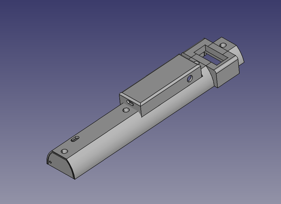
If the electric mosquito swatter is the same as the one above, you can directly print the handle design.
If it is different, you may need to design one yourself.
However, some swatters have large handles with almost nothing inside, and you can directly install the additional circuitry. Remember, we still need to find a place for the display and the speaker.
The 3D printing files can be downloaded at the end of the article.
Step 9: Assemble Everything
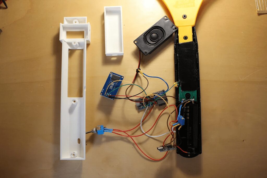
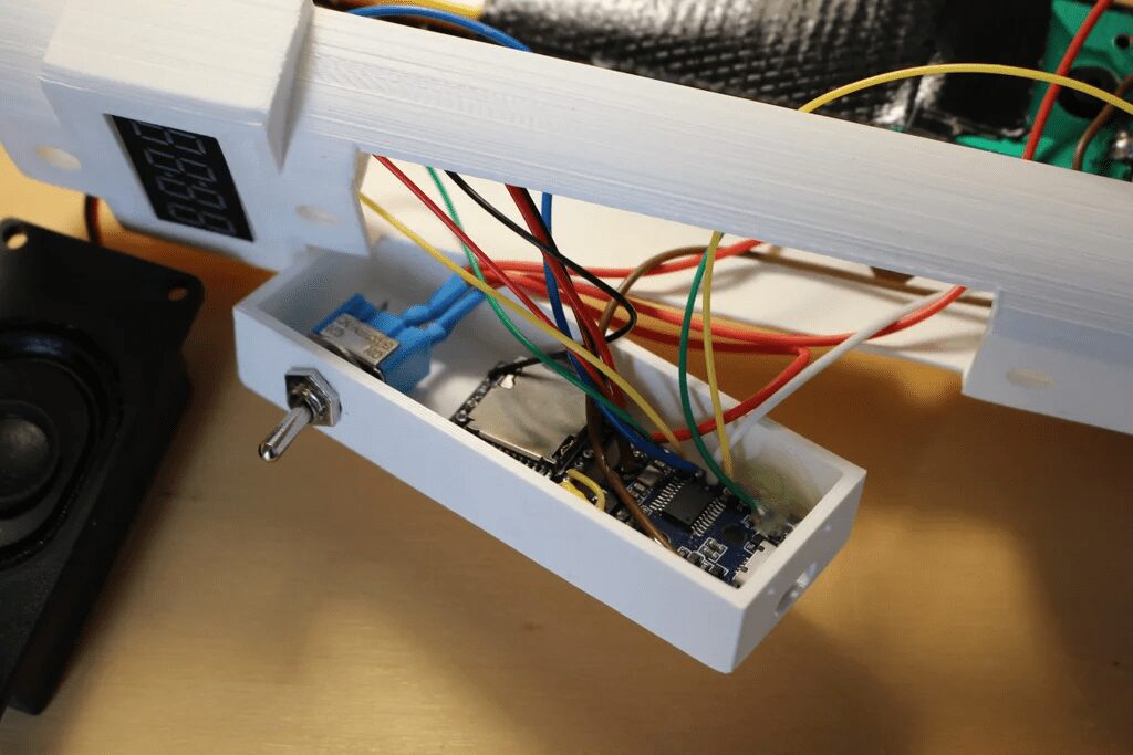
Here, use a hot glue gun to secure the parts in their final positions.
The speaker is also directly glued to the swatter.
Step 10: Where are the Mosquitoes?
Once again, if you don’t care how it works and just want to get your “ultimate” electric mosquito swatter, you can skip this step… or come back to it later.
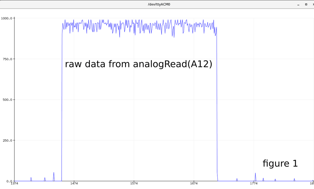
Once we solder all the components together, if we load a simple program onto the ATtiny that only does a simulated read (A12), we can check the raw data:
The raw data looks very noisy, and we cannot tell where/when there is a mosquito (or something else; I didn’t wait for a mosquito to hit my swatter to debug the code 🙂 it hit the mesh itself (see figure 1).
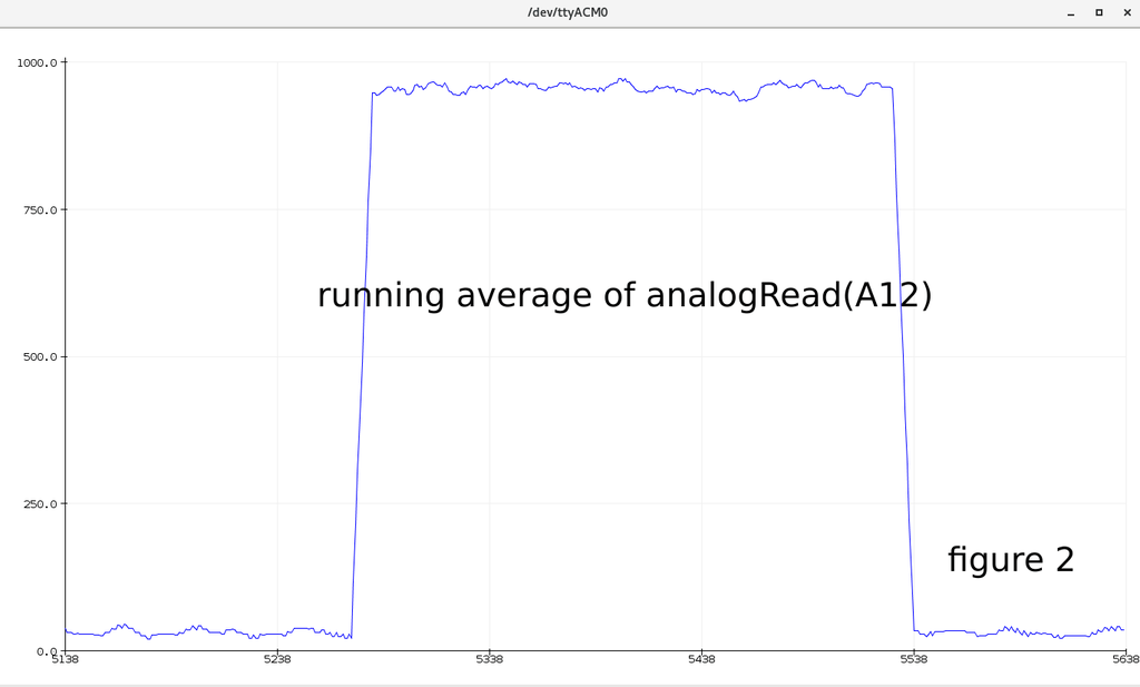
The average is a good way to clean some noise, and my idea is to compare the last average with the “long-term” average, but the results were also a bit disappointing (see figure 2).
Then learn how others do it:<span>https://www.iese.fraunhofer.de/blog/change-point-detection/</span>
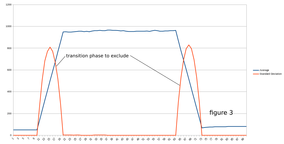
This looks exactly what we are looking for; calculating the standard deviation of the signal should allow us to detect when a mosquito has been killed (see the “Animation of change point detection via sliding window” section in the above link).
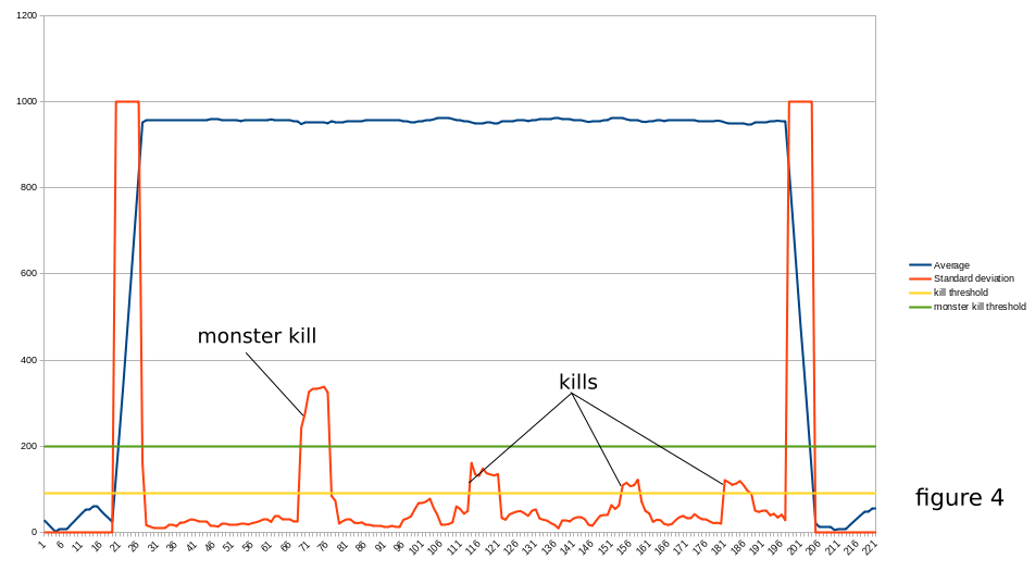
Applied to our setup, we get the following results (figure 3).
In the program, we calculate the square of the standard deviation, and we can see that when the button is pressed or released, it reaches a very high value (this is expected, the signal goes from 0V to close to 5V), but once these phases are excluded, we can monitor this standard deviation and assume that if it reaches some high value, we have an interference in the circuit, which must be a mosquito being “killed” (figure 4)!
Now we know how to determine when a “kill” has been completed, the rest is simple (play sound, increase score).
To be more accurate, we added a few things:
-
A 470uF capacitor (it provides some additional noise filtering and acts as a “power bank” when large currents are needed) -
We have a two-level averaging mechanism (in the code, we can see that we measured the voltage of pin A12 five times in its raw state, took the average, and then stored this average in a sliding window for standard deviation calculation).
Step 11: Load the Program onto the Digispark Pro
This is quite simple; you can program the ATtiny using the Arduino IDE.
Wiki:<span>http://digistump.com/wiki/Digispark/tutorials/connectingpro</span>
Some explanations of the code:
In the<span>setup()</span> function, we initialize the serial communication needed for the DFPlayer, read the potentiometer value to adjust the volume (only read once during setup, meaning the swatter needs to be turned off/on to consider the volume adjustment).
To reset the counter, if you want to reset the score to zero, you need to press the reset button, turn on the power of the swatter, and wait for the display to show “0”.
Then it will read the score stored in the EEPROM.
It sets the brightness of the display (otherwise it will remain off).
In the<span>loop()</span> function, we basically handle the average power of the swatter<span>process_average()</span> and the square of the standard deviation, which tells us whether there is lethality<span>process_std_dev()</span>.
Relevant code can be downloaded at the end of the article.
Step 12: Update the Digispark Micronucleus (Optional)
The Digispark Micronucleus is a piece of code responsible for “booting” the Digispark.
It checks whether we have uploaded a new program, and if not, it starts the already loaded program.
The problem is that it needs to wait 6 seconds, which is a long time for us to want to start our weapon to swat mosquitoes.
However, the Micronucleus has some variants with different checking mechanisms. If you follow these instructions to update the Micronucleus (using the “recommended” configuration), the swatter will be ready in a second or two.
Reference:<span>https://github.com/ArminJo/micronucleus-firmware</span>
After updating the Micronucleus firmware, reload your program.
Step 13: Troubleshooting
Hopefully, you won’t need to read this,
some tips, just in case……
1. Not working much…… check wires and solder;
2. If the electric mosquito swatter restarts itself (you hear the startup sound but it doesn’t turn on/off), charge the battery;
3. The electric mosquito swatter will automatically turn off after about 30 seconds.
-
Some USB charger circuits have an automatic standby mode (mine does, using the IP5306 chip); if the current consumption is below a certain amount (IP5306 is 45mA), it will enter standby mode. -
The first possible solution is to press the swatter button periodically… like every 20 seconds. The circuit board (with IP5306) has a “key” function that can turn the power on or off, marked with a “K” on the board. The <span>watchdog()</span>function suggested in the above code will keep the power working normally.
4. If the detection capability of the swatter is really poor or frequently misdetects… then some code adjustments may be necessary.
If you want to use the USB port to display some variables, you must modify the code to use the DigiCDC library and remove SoftSerial (used for the 4-digit display). But more importantly, when doing so, we will draw power from the USB port instead of the battery charger port, which makes a big difference… the quality of VCC greatly affects our calculated averages and standard deviations…
In other words, any adjustments made while connected to USB may fail when running on battery.
One way to obtain some small information is to use the display itself (i.e., display the last standard deviation when pressing the reset button).
Knowing this, you can try adjusting the following values in the code, which have a significant impact on our detection.
Number of samples for single reading:
int samples=10;
Size of the average sliding window:
int nbr_slot=15;
int value[16];  // array of (nbr_slot + 1)
Threshold for standard deviation:
int threshold=110;
int monster_threshold=250;
Step 14: Continue Improving the Electric Mosquito Swatter and Share Your Improvements
If you find simpler methods or designs for modifying the electric mosquito swatter, feel free to share them!
Original link: https://www.instructables.com/Ultimate-Mosquito-Swatter-Mod-for-Gamer-Add-Kill-C/
Project Author: lmu34
The translation was first published on: DF Maker Community
Hardware Arsenal
Click to learn more👆
If you have anything to say or any corrections to the article translation, feel free to leave a comment below!
All materials related to the project can be downloaded in the following ways:
1. You can click “Read Original” to download from the community forum!
2. You can reply in the background of the public account“Modified Electric Mosquito Swatter” to obtain the download file!
(Note: For previous projects, if the link is invalid, you can also search for the relevant project name on our community forummc.dfrobot.com.cn for free download)