Scan to FollowLearn Embedded Together and grow together

1. Layered ConceptThe concept of layering is not a mysterious thing; in fact, many engineers working on projects are already using it. The layered structure is indeed very useful, and once understood, it can lead to a moment of enlightenment.If I don’t understand how to drive an LCD, that’s easy; I can look at the datasheet, refer to someone else’s code, and quickly get it done. However, if I don’t understand the principles of program design, it can lead to a lot of confusion during the project.After reviewing various embedded books on the market, including MCS-51, AVR, ARM, etc., I found that none of them introduce design concepts; even if there are, they are rare. Writing code is not difficult, but writing good and efficient code requires some experience. The principles of structured and modular programming are the most basic requirements.But how do we apply abstract concepts to engineering practice? This requires going through trials during project work, summarizing experiences, and abstracting them into theories, which greatly benefits the accumulation of experience and the dissemination of technology.
One is the “time-slicing design concept,” which is very useful for solving multitasking problems in practice. This can usually be used to determine whether a person is a microcontroller learner or a microcontroller engineer. This must be mastered. (It will be introduced below).
The second is the “layered masking design concept,” which is the layered concept. Below, I will use the example of a keyboard scanning program to introduce today’s topic.
Problem StatementMicrocontroller learning boards generally simplify things by assigning keys well, for example, the entire 4*4 keyboard matrix is assigned to port P1, with 8 control lines, just right. This makes the program very easy to write. You only need to do something simple: KEY_DAT = P1;and the port data is read in.Indeed, reality is not so good. In actual project applications, the multiplexing of microcontroller pins is quite significant, which is very different from those so-called microcontroller learning boards.Another reason is that the general design process is “software cooperating with hardware”; simply put, it means first determining the hardware schematic, then the hardware wiring, and finally the software development. Because modifying hardware is relatively troublesome, while software modifications are easier. This is the traditional yin-yang balance philosophy in China. Hardware design and software design are inherently at odds; one cannot have both. Making hardware design convenient may cause significant trouble in writing software.Conversely, making software design convenient can also complicate hardware design. If both hardware and software designs are made convenient, there are only two possibilities: either the design is very simple, or the designer has reached a very high level. We will not consider so many situations; we will look at the problem purely from the perspective of common practical applications.For the convenience of wiring, hardware often assigns IO ports to different ports. For example, the aforementioned 4*4 keyboard, with 8 wires assigned to P0, P1, P2, and P3. Then, the scanning keyboard programs for development boards can go to hell. How do you scan the keys? I remember when I first started learning, I had to write three very similar programs, scanning each key one by one…Perhaps some are unwilling to accept, “Those things I spent a long time learning and using well, how can you say they are useless?” Although it sounds a bit cruel, I still want to say, “Brother, accept reality; reality is cruel…”However, the difference between humans and lower animals is that humans can create. When faced with difficulties, we think of ways to solve them, and thus we begin to ponder…Finally, we introduce the concept of “mapping” learned in middle school mathematics to solve the problem. The basic idea is to map keys from different ports to the same port.Thus, the key scanning program is divided into three layers:1) The lowest layer is the hardware layer, which completes port scanning, 20ms delay for debouncing, and maps the port data to a KEY_DAT register, which serves as an interface to the upper driver layer.2) The middle layer is the driver layer, which only operates on the value of the KEY_DAT register. Simply put, regardless of how the underlying hardware is wired, the driver layer does not need to care; it only needs to care about the value of the KEY_DAT register. The indirect effect of this is that it “masks the differences in underlying hardware,” so the programs written for the driver layer can be reused.The driver layer also provides a message interface for the upper layer. We use a concept similar to window program messages here. It can provide some key messages, such as: key press message, key release message, long press message, long press step message, etc.3) Application layer. Here, we write key function programs according to different project requirements, which belong to the top layer of the program. It uses the message interface provided by the driver layer. The idea of writing programs at the application layer is that I do not care how the lower layer works; I only care about key messages. When a key message comes, I execute the function; when there is no message, I do nothing.Below is a simple common example to illustrate the use of this design concept.When adjusting the stopwatch time, it requires holding down a certain key to continuously increase the time. This is very practical and widely used in actual household appliances.Before looking at the following, everyone can think about whether this is difficult? I believe everyone will answer loudly, “Not difficult!!” However, I ask again: “Is this troublesome?” I believe many people will say, “Very troublesome!!” This reminds me of when I first learned microcontrollers and wrote such key programs with messy structures. If you don’t believe it, you can try writing it with 51; that way, you can better appreciate the advantages of the layered structure discussed in this article.Project Requirements:Two keys, assigned to P10 and P20, are the “increase” and “decrease” keys, requiring continuous increase and decrease functionality when the key is pressed.Practical Implementation:Assuming the keys are pulled up, with a high level when no key is pressed and a low level when a key is pressed. Additionally, to highlight the problem, the debounce program is not included here; it should be added in actual projects. The C language function parameter passing is diverse; here, as an example, the simplest global variable is used to pass parameters. Of course, you can also use unsigned char ReadPort(void) to return a read key result, or even void ReadPort(unsigned char* pt) to use a pointer variable to pass the address to directly modify the variable. There are many methods, and this depends on each person’s programming style.1) Start writing the hardware layer program to complete the mapping
#define KEY_MIN  0X01
#define KEY_PLUS  0X01
unsigned char KeyDat;
void ReadPort(void) {
    if (P1 & KEY_PLUS == 0) {
        KeyDat |= 0x01;
    }
    if (P2 & KEY_MIN == 0) {
        KeyDat |= 0x02;
    }
}
C language should be easy to understand, right? If KEY_PLUS is pressed, the P10 port reads a low level, so P1 & KEY_PLUS results in 0 (xxxx xxx0 & 0000 0001), satisfying the if condition, entering KeyDat |= 0x01, which means setting bit0 of KeyDat to one, that is, mapping KEY_PLUS to bit0 of KeyDat.KEY_MIN is similarly mapped to bit1 of KeyDat; if bit0 of KeyDat is 1, it indicates that KEY_PLUS is pressed, and vice versa.There is no need to think of it as mysterious; mapping is just that. If there are other keys, use the same method to map them all to KeyDat.2) Writing the driver layer programIf you think of KeyDat as port P1, then isn’t this the same as the standard scanning program for learning boards? Yes, that is the purpose of the underlying mapping.3) Writing the application layer programAccording to the message, the hardware layer must be separated; however, the requirements for the driver layer and application layer are not so strict. In fact, for some simple projects, it is unnecessary to separate these two layers; just respond flexibly according to practical applications.In fact, writing programs this way is very convenient for portability; by appropriately modifying the hardware layer ReadPort function according to different boards, the driver layer and application layer can use a lot of code without modification, greatly improving development efficiency. Of course, this key program will have certain issues, especially in cases of mixed use of normally closed keys and momentary keys. This is left for everyone to think about; after all, problems can always be solved, although some methods are better than others.2. Time-Slicing Design ConceptLet’s start with a small example to introduce this topic. Imagine a basic household appliance control board, which will certainly include: LED or seven-segment display, keys, relays, or SCR outputs in varying degrees. The seven-segment display requires dynamic scanning every 10ms to 20ms, and keys also need about 20ms of debounce delay. Have you realized that these times are actually happening simultaneously?Recall how our textbooks taught us to debounce keys? That’s right, a dead loop, absolutely a stationary dead loop, using instructions to time. This naturally raises a question: if the microcontroller is stuck in a dead loop, what about other tasks? What about the dynamic scanning of the seven-segment display?We can only wait until the key scanning is done, which results in the seven-segment display flickering; if the scanning time is too long, shortening the debounce time for keys is not a solution. Imagine if we had many other tasks to do simultaneously?One solution is today’s theme, the time-slicing scanning concept. Of course, it is not the only solution; I have been using it and find it to be a very good concept that can solve many practical problems. Boldly speaking, the time-slicing scanning concept is also one of the core ideas in microcontroller programming; whether you believe it is up to you.Implementation of the Core Idea:Actually, it involves several stepsFirst, use RTC interrupts for timing; I prefer a short RTC interrupt time of 125us, which is necessary for decoding infrared remote control. RTC timing is quite accurate, so we should make the most of it.Second, place three (number can be defined) timers in the RTC interrupt service routine (essentially counters). My habit is to use 2ms, 5ms, and 500ms as benchmark times, which are provided for the entire system to call, so they must be accurate. In practice, use an oscilloscope to adjust them, which is not difficult.Third, place a dedicated time processing subroutine in the main program loop. (Note: The microcontroller does not stop; it is always running in a continuous loop, which is somewhat different from what is taught in school; I have been asked this question in interviews…). All time processing is done in the time processing subroutine, which is very convenient. A microcontroller system needs to handle at least 10 to 20 different times, and it requires 10 to 20 timers, many of which need to work simultaneously and asynchronously. If each were handled separately, it would be quite troublesome.Fourth, “the program runs to wait, not stands still to wait”; this sounds a bit mysterious. An engineer who joined the company with me mentioned this issue, and I think it is also a relatively important idea of the time-slicing system, so I call it that. Below, I will elaborate.Fifth, let’s let the program speak; comments should be as detailed as possible. You can understand the code without looking at it, just by reading the comments.(1) First, the interrupt service routine part:Interrupt every 125us————Generate several benchmark times—–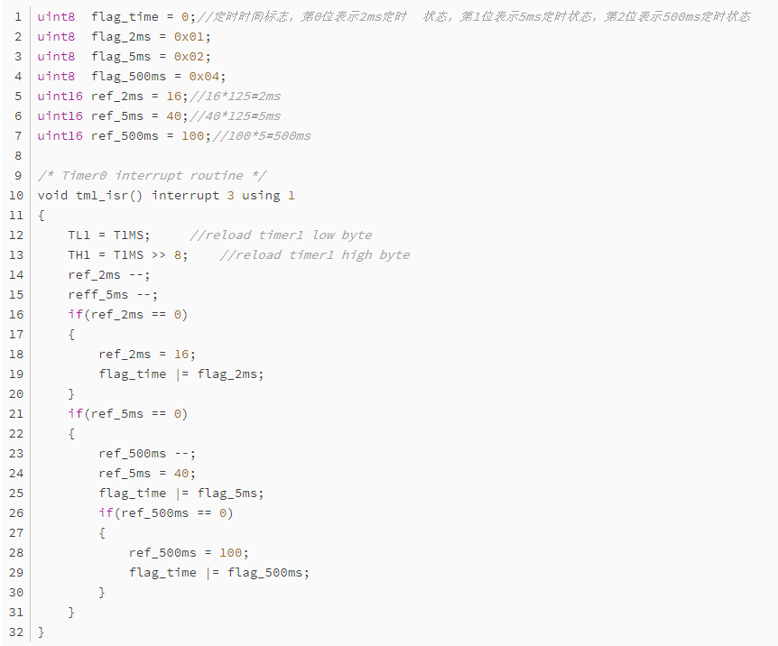
(1) The ref_2ms register continuously decrements by 1, reducing by 1 every interrupt, totaling 16 reductions, so the time elapsed is 125us × 16 = 2ms, which is the so-called timer/counter. This allows us to use one system RTC interrupt to achieve many timing requirements.(2) Set the 2ms timer end flag, which is provided for the time processing program; this is a framework for a timer, and the 5ms timer is exactly the same.
This program also uses a block framework, which is quite convenient, but it is unrelated to today’s topic. The above program is the timer in the interrupt service routine, which times 2ms, 5ms, and 500ms, and the overflow is recorded by the flag_time flag. The program can read this flag to know whether the timing has reached.
(2) Now let’s look at the unified time service subroutine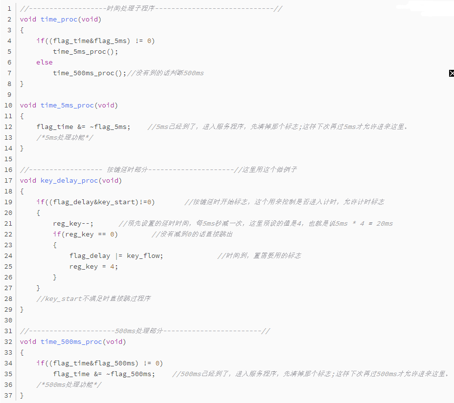 Here, we used the key debounce timer of 20ms as an example. Once understood, we can completely mimic that timer and place many more timers below. Each timer counts simultaneously, and whoever finishes counting first shuts itself down and sets the corresponding flag for other programs to call, without affecting other timers!In this way, we can place many timers here; generally speaking, having ten or so is not a problem, fully meeting the needs of a microcontroller system for multiple timing requirements.The structure of a single timer is quite simple: first, check whether the timing flag is allowed to enter timing, then a dedicated register increments or decrements by 1. After adding or subtracting the corresponding value, when the corresponding time is reached, the timer is turned off, and the corresponding flags are set.At this point, we can obtain all the required times; isn’t this very convenient? Let’s take a look at what the microcontroller is doing during this time.Only when the interrupt timing reaches 5ms or 500ms is the overflow flag valid, allowing entry into the above timing program; other times are spent doing other tasks. Moreover, when entering the above timer, it is clear that it is not stuck in a dead loop; it simply increments or decrements a register and exits, which takes an extremely short time, probably around 5us to 20us, having no impact on the execution of the main program.(3) Now let’s see how to call it specificallyThe key debounce time processing issue discussed earlier can now be addressed using the method introduced above. Key processing is also an important foundational knowledge, but it is not within the scope of this discussion, so we will only discuss how to solve the timing issue, and we can continue discussing some key issues next time.
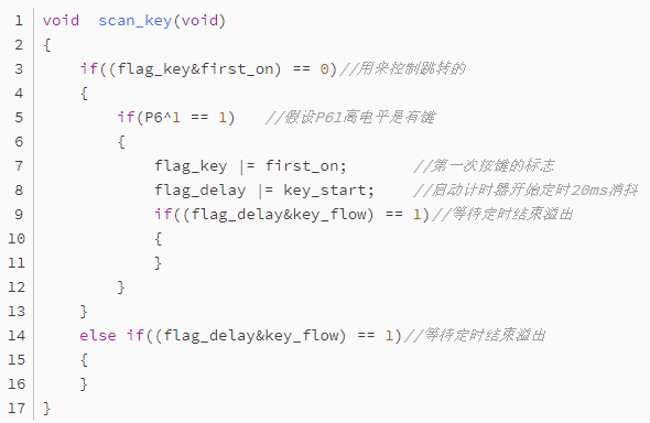 It goes something like this: determine when a key is present; if not, exit; if so, start the debounce timing. On the second entry, directly control the judgment of whether the time is sufficient through the flag bit.Similarly, in waiting, this is the last point mentioned: we are running to wait, not standing still to wait. Compared to dead loop timing, during the time before the 20ms timing, what is the microcontroller doing?
In a dead loop, it is certainly waiting in place, doing nothing. However, looking at the above program, it only checks whether the timing is sufficient; the specific timing is done in the unified time subroutine. If the timing has not yet reached, it exits and continues running other programs, until the time arrives, at which point the microcontroller determines that flag_delay and key_flow meet the conditions and begins to enter the key processing program. During this period, the microcontroller is doing other tasks, and the main loop only checks once, so the microcontroller has plenty of time to run other programs without wasting time on debouncing.
(4) Let’s take a look at my main program loop
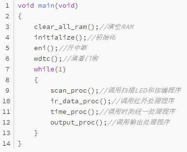 This is the loop body; all functions are made into subroutine forms, and they can be attached as needed, which is quite convenient. In this way, a total loop body, the microcontroller is constantly executing this loop body. If the entire program adopts the time-slicing scanning concept mentioned above, the time for one loop is quite short. Isn’t it somewhat similar to the computer’s approach?A computer, no matter how fast, does not process multiple tasks simultaneously; rather, it processes one at a time, and at a very fast speed, creating the illusion that it is processing multiple programs simultaneously. I think what I ultimately want to express is just this.In my view, with this idea supporting it, programming for microcontrollers becomes relatively easy; the remaining task is to focus on using the program to implement our ideas.Of course, this is just one feasible method; it does not mean that there is only this method. If anyone has good ideas, please share them!Writing programs is an art; it is easy to write them, but writing them well and elegantly is quite difficult.
Source: Internet, copyright belongs to the original author. If there is any infringement, please contact for deletion.

Follow me 【Learn Embedded Together】 to become better together.
If you find the article good, click “Share“, “Like“, or “Recommend“!