15.3.2
Software Design
15.3.2.1
Create a New Project
For the e2 studio development environment: Copy our previous e2s project“11_GPIO_LED”, then rename the project folder to“16_ICU_External_IRQ”, and finally import it into our e2 studio workspace.
For the Keil development environment: Copy our previous Keil project“11_GPIO_LED”, then rename the project folder to “16_ICU_External_IRQ”, and double-click the Keil project file inside that folder to open the project.
After creating the project, create a new folder named “key” under the “src” folder in the project root directory, and then create the source file and header file inside the “key” folder:“bsp_key_irq.c” and “bsp_key_irq.h”. The project file structure is as follows.
List 1: File Structure
Swipe left or right to view the complete content
16_ICU_External_IRQ├─ ......└─ src├─ led│ ├─ bsp_led.c│ └─ bsp_led.h├─ key│ ├─ bsp_key_irq.c│ └─ bsp_key_irq.h└─ hal_entry.c15.3.2.2
FSP Configuration
First, open the FSP configuration interface for the“16_ICU_External_IRQ” project, and then we need to configure the chip’s pins and their corresponding functions in this interface.
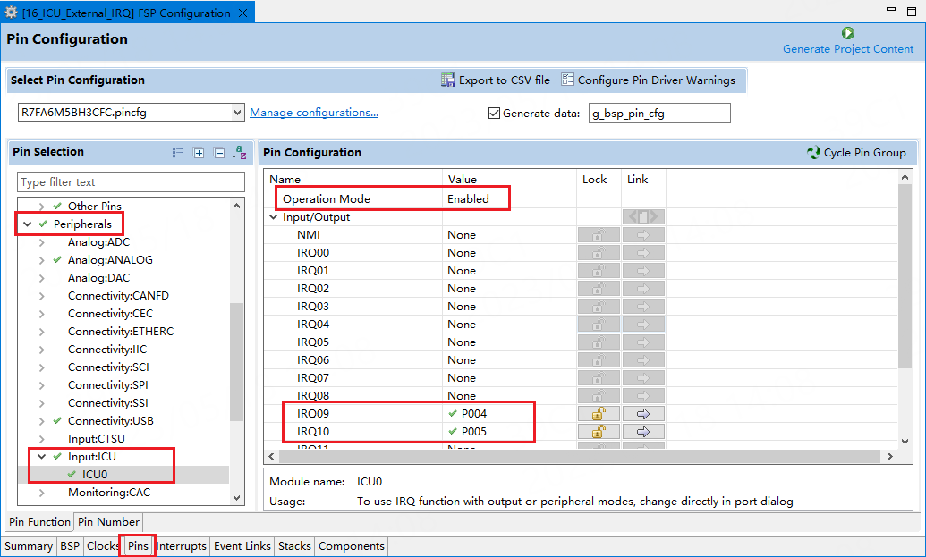
Taking the Wildfire Qiming 6M5 development board as an example, first configure the pins connected to the ICU’s interrupt channels.
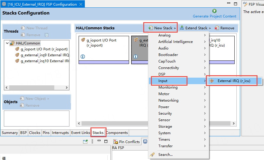
Then, click“Stacks” -> “New Stack” -> “Input” -> “External IRQ” to add the external interrupt module, as shown in the figure below. Since two buttons are used, two external interrupts are needed, so we need to add 2 external interrupt modules here.
The first external interrupt module is configured for button 1’s external interrupt, set as shown in the figure below:
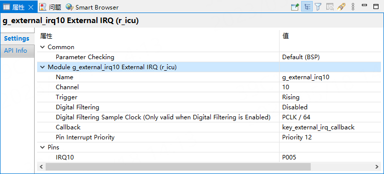
The second external interrupt module is configured for button 2’s external interrupt, set as shown in the figure below:
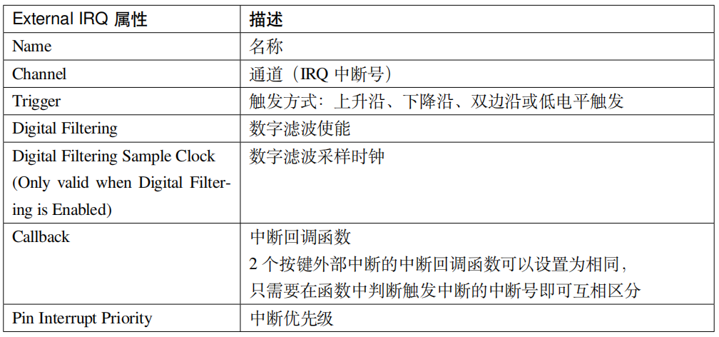
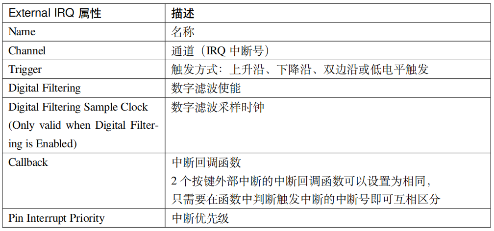
The properties of the external interrupt module (r_icu) are introduced in the table below.
List 4: External IRQ Property Introduction
After the configuration is complete, you can press the shortcut key “Ctrl+S” to save, and finally click the button in the upper right corner“Generate Project Content” to let the software automatically generate the configuration code.
15.3.2.3
Button External Interrupt Initialization Function
List 2: Code Listing 16_1: External Interrupt Initialization Function
Swipe left or right to view the complete content
/* KEY External Interrupt Initialization Function */void Key_IRQ_Init(void){fsp_err_t err = FSP_SUCCESS;/* Open ICU module */err = R_ICU_ExternalIrqOpen(&g_external_irq9_ctrl, &g_external_irq9_cfg);err = R_ICU_ExternalIrqOpen(&g_external_irq10_ctrl, &g_external_irq10_,→cfg);/* Enable Interrupt */err = R_ICU_ExternalIrqEnable(&g_external_irq9_ctrl);err = R_ICU_ExternalIrqEnable(&g_external_irq10_ctrl);}-
R_ICU_ExternalIrqOpen() is used to open an instance of an external interrupt module.
-
R_ICU_ExternalIrqEnable() is used to enable the external interrupt, which can then trigger the external interrupt.
15.3.2.4
Button Interrupt Callback Function
Since the Callback attribute configured in the previous FSP configuration is the same for both interrupts, we only need to implement one interrupt callback function. Of course, the interrupt callback function can also be set to two different functions, as defined by the user.
Both buttons share the key_external_irq_callback interrupt callback function, and the p_args->channel parameter is used to determine which interrupt channel triggered the interrupt, thus identifying which button was pressed. The function is as follows:
List 3: Code Listing 16_2: Button Interrupt Callback Function
Swipe left or right to view the complete content
/* Button Press Flag */volatile bool key1_sw2_press = false;volatile bool key2_sw3_press = false;/* Button Interrupt Callback Function */void key_external_irq_callback(external_irq_callback_args_t *p_args){/* Determine Interrupt Channel */if (9 == p_args->channel){key1_sw2_press = true; // Button KEY1_SW2 pressed}elseif (10 == p_args->channel){key2_sw3_press = true; // Button KEY2_SW3 pressed}}15.3.2.5
hal_entry Entry Function
The hal_entry entry function is as follows:
List 4: Code Listing 16_3: hal_entry Entry Function
Swipe left or right to view the complete content
/* User Header File Inclusion */#include "led/bsp_led.h"#include "key/bsp_key_irq.h"extern volatile bool key1_sw2_press;extern volatile bool key2_sw3_press;void hal_entry(void){/* TODO: add your own code here */LED_Init(); // LED InitializationKey_IRQ_Init(); // KEY External Interrupt Initializationwhile(1){/* Check if Button KEY1_SW2 is pressed */if (key1_sw2_press){key1_sw2_press = false; // Clear FlagLED2_TOGGLE; // Toggle LED2}/* Check if Button KEY2_SW3 is pressed */if (key2_sw3_press){key2_sw3_press = false; // Clear FlagLED3_TOGGLE; // Toggle LED3}// LED1 blinks to indicate the program is runningLED1_TOGGLE;R_BSP_SoftwareDelay(1, BSP_DELAY_UNITS_SECONDS); // Delay 1 second// After the button is pressed and triggers the interrupt, LED2 or LED3 will be delayed for up to 1 second to toggle}}#if BSP_TZ_SECURE_BUILD/* Enter non-secure code */R_BSP_NonSecureEnter();#endif}15.3.3
Download Verification
Download the compiled program to the development board and reset it. Press user button 1 and button 2 to control the LED2 and LED3 lights respectively. Meanwhile, LED1 light toggles every second.


Need Technical Support?
If you have any questions while using Renesas MCU/MPU products, you can scan the QR code below or copy the URL into your browser to access theRenesas Technical Forum for answers or to get online technical support.

https://community-ja.renesas.com/zh/forums-groups/mcu-mpu/
To be continued
Recommended Reading

Overview of Interrupt Applications in RA Series MCUs – Practical Guide to Renesas RA Series FSP Library Development (35)

NVIC Interrupt Configuration Firmware Library & RA6M5 – Practical Guide to Renesas RA Series FSP Library Development (36)

External Pin Interrupt – Practical Guide to Renesas RA Series FSP Library Development (37)