Smart Tracking Car with Cargo Transport Function Based on Arduino Platform
01
Project Background
First, let’s talk about the background of this project! It was born during my engineering course project, and the tasks it aims to solve are as follows:
1. Phase One: The main task is to autonomously move from the starting point to the destination by any means necessary, with two possible paths:
The first, is to choose to go around the step obstacle and simply follow the line to the destination (the requirement is simple but the distance is long, total distance of 3.6 meters);
The second is to cross the step directly, which has two levels with a height of 2 cm. This requires higher demands on the task subject, as it not only needs to climb over but also must accurately find a line to reach the destination (the requirement is high, but the distance is greatly shortened to about one meter).
2. Phase Two: Carry the white cylinder located at the starting point to the destination and place it down. The method of “grabbing” the object can be various, each showcasing their own skills!!! (A little preview, our method is truly unique and profound, DDDD)
02
Building Section (Basic Structure)
Materials Needed:
1. Arduino Mega2560
Arduino is a convenient, flexible, and easy-to-use open-source electronic prototyping platform, characterized by low barriers to entry and high expandability, making it very suitable for beginners to start open-source projects. Here, we use it as the “brain” to control our car.
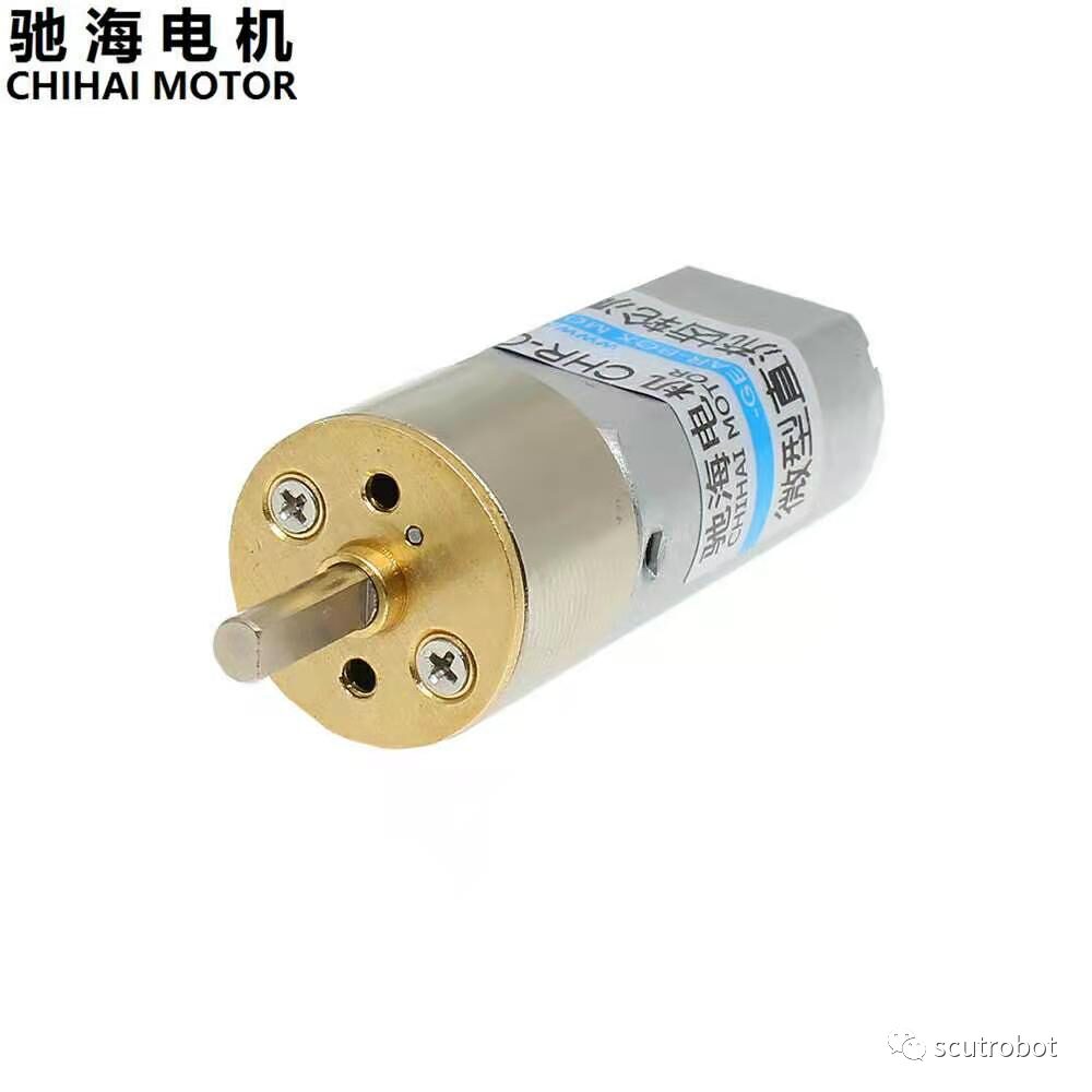
2. CHR16GR050 Chihai Motor 6V
To pursue the stability of the car, we decided to use a higher quality Chihai motor, and to achieve a balance between speed and power, we selected a reduction ratio of 1:150 according to the motor parameter table, which can still output sufficient power at a relatively fast speed. The significance of this reduction ratio is that when the original speed and power of a motor are constant, the larger the reduction ratio, the greater the output force.

3. Acrylic Board
We chose a 3 mm thick acrylic board as the material to make the main body of the car. We can use a laser cutter to process it to create the base we need. (Sigh, the awful smell during the processing is something I’ll never forget in my life)
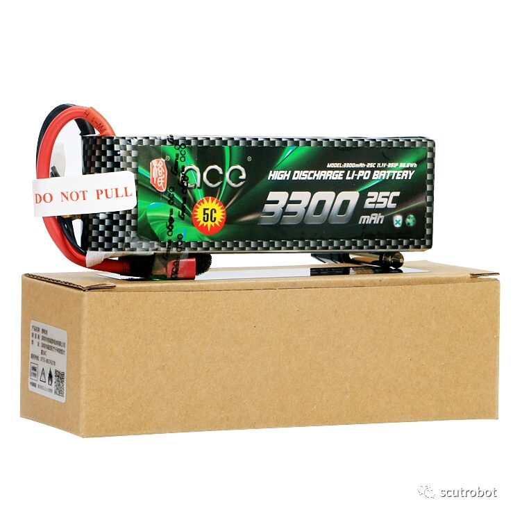
4. Format Lithium Battery 7.4V 5C
Considering that this battery needs to power four motors and two 20KG class servos as well as various sensors, we chose a format lithium battery for model aircraft (one is better than six, manual dog head), with a 5C discharge rate that is sufficient for our power-hungry “big consumer”.
5. L298N Motor Driver Board
I chose the classic L298N driving module, which can meet our needs and can convert the high voltage of the battery to the 5V and 3.3V needed to power the motors. Due to space constraints, I won’t elaborate on this here; please refer to the following article for specific usage methods.
“Arduino’s L298N Motor Driver Module”
6. TCRT5000 Five-Way Tracking Photoelectric Sensor and Four 4cm Diameter Small Wheels
7. RDS3115 Digital Servo 15KG
It has strong stability, is not easily shaken or worn, and has relatively high precision.
8. Various tools and parts such as Dupont wires, soldering irons, etc., are also needed for this type of practical project.
The assembled product (Phase One) is shown in the figure below
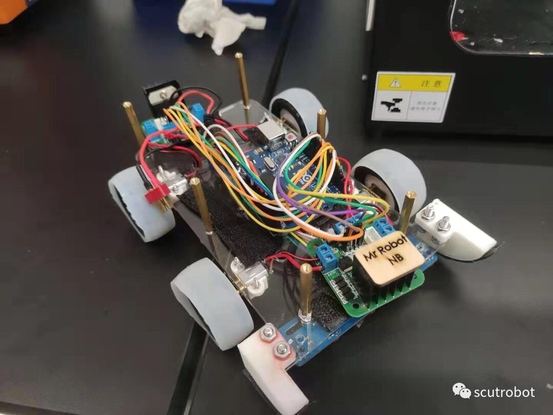
The assembled product (Phase Two) is shown in the figure below

03
Line Following Section
1. Materials Needed:
(1) Five-Way Tracking Photoelectric Sensor: As the “eyes” of the car, it tells the car the current position status (head tilted left, right, encountering a corner…)

(i) Working Principle: The infrared emitting diode of the TCRT5000 sensor continuously emits infrared rays. When the emitted infrared rays are not reflected back or are reflected back but not strong enough, the phototransistor remains off, indicating that the output of the module is low, and the indicator diode remains off; when the detected object appears within the detection range, the infrared rays are reflected back with sufficient strength, saturating the phototransistor, and the output of the module becomes high, indicating that the diode is lit.
Since black has a strong absorption capability, when the infrared rays emitted by the tracking module hit the black line, the infrared rays will be absorbed by the black line, causing the phototransistor on the tracking module to be off, and the corresponding LED on the module will turn off (at this time, the photoelectric feedback value is 1). When no black line is detected, the corresponding LED on the module remains lit (at this time, the photoelectric feedback value is 0).
(ii) Advantages: The five-way integrated photoelectric sensor is simpler to operate than a single photoelectric sensor, occupying fewer pins on the Mega board (only two power pins needed), but it is not as flexible, with fixed spacing, and each photoelectric sensor does not have a potentiometer to adjust its sensitivity. If one fails, all five need to be replaced (the failure rate is a bit high, it depends on luck). However, we can adjust the height of the five-way tracking photoelectric sensor from the ground to adjust its sensitivity. Based on practical experience, this type of photoelectric sensor is generally suitable at a distance of 1.5~3 cm from the ground. This can be adjusted based on actual conditions.
(2) Black Electrical Tape: The black tape is used to build the “track” for the car to run on, with a width of 1.8cm.
2. Algorithm Control:
The TCRT5000 integrated five-way photoelectric sensor has seven pins: out1~5, GND, 5V, where the first five correspond to the five photoelectric sensors, and the last two are power supply pins. You can regard GND as the negative pole and 5V as the positive pole. Now we can connect OUT1~5 to the digital pins 2~6 on the Mega board.
The control code (excerpt) is as follows:

Code Explanation:
The following readLine function can read the photoelectric values from each sensor and store them in five array variables, val[0]~val[4] corresponding to photoelectric sensors 1 to 5, and the getval() function’s role has already been commented above in the main code.

The five-way photoelectric sensor can have the following six situations, where “1” indicates detecting a black line, “0” indicates not detecting a black line, and “0/1” means 0 or 1 (of course, this is the ideal state; when the photoelectric sensor’s recognition is not satisfactory, you can adjust its height from the ground appropriately). These correspond to the six movement strategies of the car. Additionally, the following five array variables correspond to photoelectric sensors 1 to 5, starting from 0.

Tips: Here, I would like to add that ideally, when the car’s sensors 1 and 5 simultaneously detect the black line, the car will execute the sixth scenario shown above—stop. However, reality often plays tricks on you (sigh, the baby is suffering!). Due to the car’s final position when it recognizes the horizontal black line at the finish line, it may have a misalignment issue, which could lead to the car mistakenly entering a large left or right turn state.
To address this, we racked our brains and finally came up with a better solution, taking the LargeTurnL code as an example:

When in a large left turn cycle, if the fifth photoelectric sensor (the rightmost sensor from the car’s perspective) detects a black line, it means the car has actually reached the finish line. However, due to the misalignment of the car’s body, the first photoelectric sensor detects the black line first, leading to a false large left turn state. At this point, the car needs to exit this state and directly determine that it is at the finish line and stop.
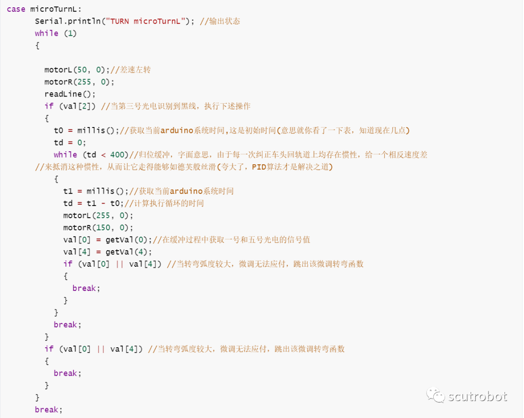
The following code explains another small detail after the car adjusts itself each time—Return Buffer
3. Small Innovation in Crossing Obstacles

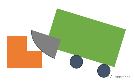
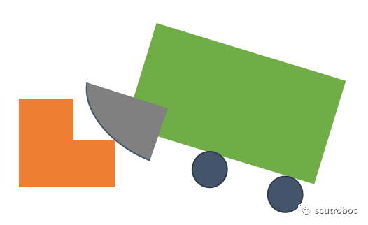
Due to the limitation of the car’s wheel diameter to 4 cm and the size of the motor, this results in a low ceiling for the output power. The step height is 2 cm, and the car weighs 1 KG, so directly charging up the step obstacle is a challenging and unstable action. Therefore, we designed a small horn to assist the car in climbing, allowing it to smoothly and easily ascend the stairs.
Moreover, it will have a certain physical correction direction function, as when the car’s head is tilted, one side of the horn will contact the step first, and the resulting resistance will cause the other side to quickly catch up, thus achieving the physical correction direction function (a happy accident).
04
Grabbing Section (Combined with Image Recognition)
This part is undoubtedly the most innovative aspect of our car!!!
1. “Balloon Doll Machine”
First is the innovation in the way of obtaining objects. We broke the traditional method of grabbing objects with a gripper; the following is the iteration diagram of the gripper.
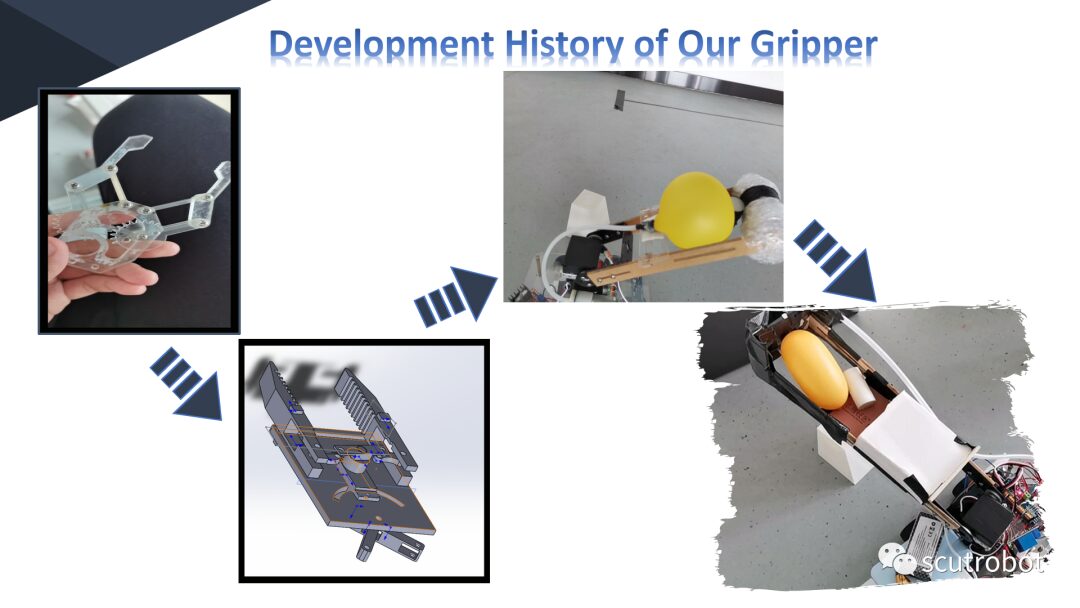
Instead, we adopted the following method, which we call the “Balloon Doll Machine.” Without further ado, let’s go straight to the video.
2. Image Recognition
Additionally, we also used the Erha image recognition sensor (hereinafter referred to as “Erha”) to identify objects, thereby adjusting the servo angle based on the obtained information to accurately “fit” the object.
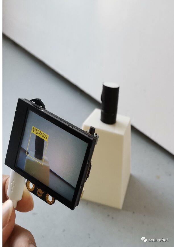
Working Principle:
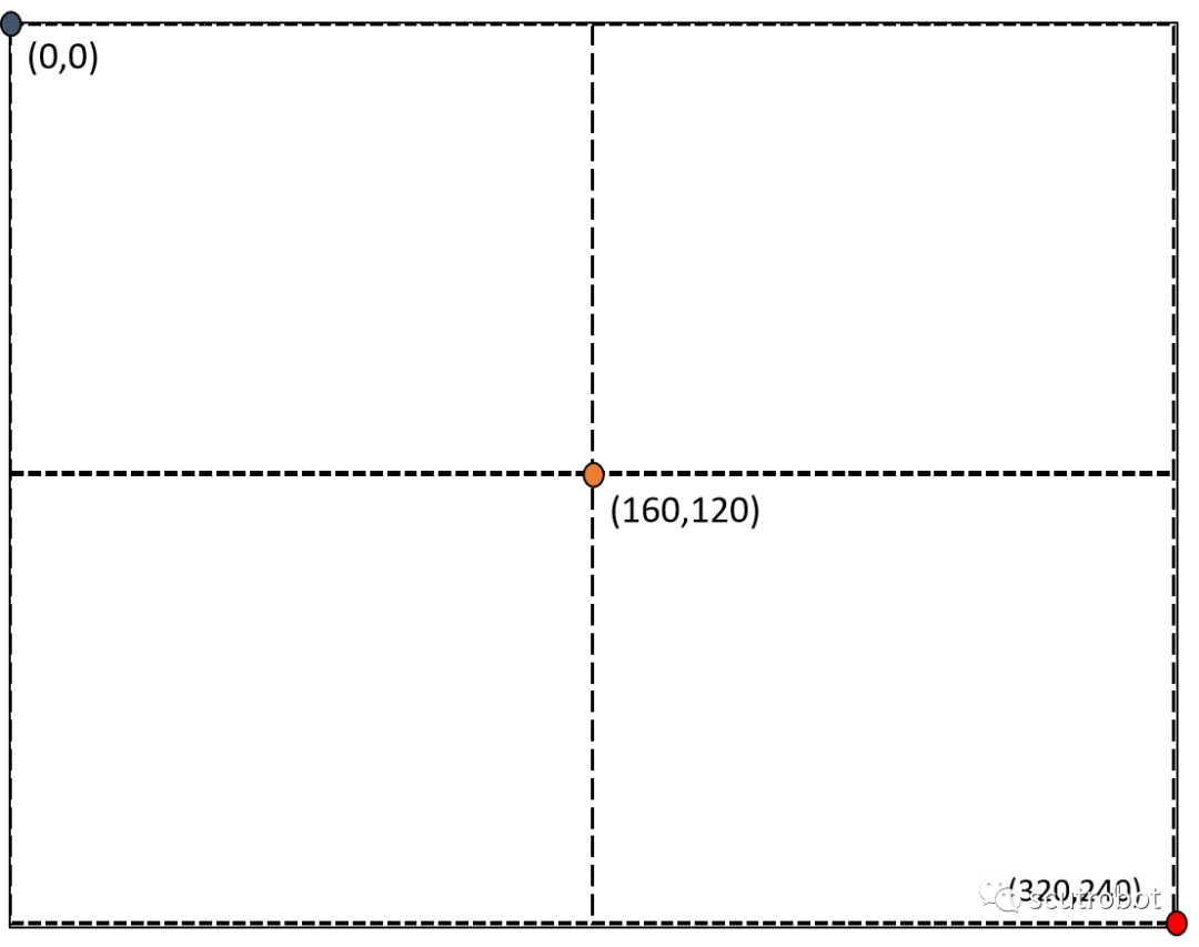
The image on the screen is the perspective of the Erha image recognition sensor, equivalent to a plane coordinate system. Each position on the screen has a corresponding coordinate. We installed it on the side of the car facing the object. Since the height of the object is fixed, we only consider the parameters of the x-axis. When the Erha recognizes an object, it transmits the x value of the object’s center position on the screen to the Arduino Mega board, allowing the car to know its relative position and adjust the servo angle to accurately “fit” the object.
Due to space constraints, I won’t elaborate on how to implement this function specifically here. If you are interested, you can refer to the following link to understand the specific usage of the Erha and library functions!
Gravity HUSKYLENS AI Camera
Erha Image Recognition Sensor Library Functions
If you have any questions, feel free to leave a message!!!

Text by | Mai Pengfei
Layout by | Liu Junhang