
Welcome to the screen series course. In this series, you will learn how to control the screen with assembly code on the Raspberry Pi, starting with displaying random data, then learning to display a fixed image and text, and finally formatting numbers as text. It is assumed that you have completed the OK series courses, so some knowledge that appears in this series will not be repeated.
The first lesson of the screen course teaches you some basic theories about graphics and then uses these theories to display a pattern on a screen or TV.
1. Getting Started
It is expected that you have completed the OK series courses, as well as the functions called in the gpio.s and systemTimer.s files in that series. If you have not completed these, or if you prefer a perfect implementation, you can download the OK05.s solution. You will also need to use the code from the start of the main.s file up to the line containing mov sp,#0x8000. Please delete everything after this line.
2. Computer Graphics
As you may realize, fundamentally, computers are very stupid. They can only execute a limited number of instructions and can only do some math, but they can also do many, many things in some way. Among these things, what we want to know right now is how computers display an image on the screen. How do we turn this problem into binary? The answer is quite simple; we design some encoding methods for each color, and then we save an encoding for each pixel on the screen. A pixel is a very small dot on your screen. If you get close enough to the screen, you might be able to distinguish individual pixels on your screen, and see that each image is made up of these pixels.
There are several ways to represent colors as numbers. Here we focus on the RGB method, but HSL is also a commonly used alternative.
With the advancement of the computer age, people wanted to display increasingly complex graphics, leading to the invention of the concept of graphics cards. A graphics card is a second processor used by your computer to specifically draw images on the screen. Its job is to convert pixel value information into brightness levels displayed on the screen. In modern computers, graphics cards can do even more complex tasks, such as rendering three-dimensional graphics. However, in this series of tutorials, we will only focus on the basic use of graphics cards; obtaining pixels from memory and displaying them on the screen.
No matter which method is used, an immediate question that arises is the color encoding we are using. There are several options, each producing different output quality. For completeness, I will simply outline them here.
| Name | Unique Color Count | Description | Example |
|---|---|---|---|
| Monochrome | 2 | Each pixel uses 1 bit to save, where 1 represents white and 0 represents black. |  |
| Grayscale | 256 | Each pixel uses 1 byte to save, using 255 to represent white, 0 to represent black, and all values in between represent a linear combination of these two colors. | 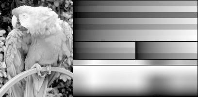 |
| 8 Colors | 8 | Each pixel uses 3 bits to save, with the first bit representing the red channel, the second bit representing the green channel, and the third bit representing the blue channel. |  |
| Low Color Value | 256 | Each pixel uses 8 bits to save, with the first three bits representing the intensity of the red channel, the next three bits representing the intensity of the green channel, and the last two bits representing the intensity of the blue channel. | 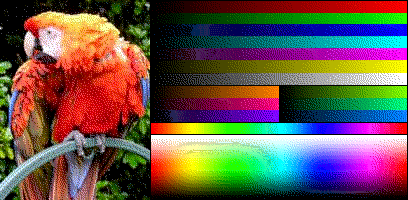 |
| High Color Value | 65,536 | Each pixel uses 16 bits to save, with the first five bits representing the intensity of the red channel, the next six bits representing the intensity of the green channel, and the last five bits representing the intensity of the blue channel. | 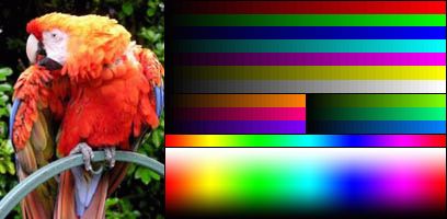 |
| True Color | 16,777,216 | Each pixel uses 24 bits to save, with the first eight bits representing the red channel, the second eight bits representing the green channel, and the last eight bits representing the blue channel. |  |
| RGBA32 | 16,777,216 with 256 levels of transparency | Each pixel uses 32 bits to save, with the first eight bits representing the red channel, the second eight bits representing the green channel, the third eight bits representing the blue channel. The transparency channel is only considered when one image is drawn over another; a value of 0 means the color of the image below, a value of 255 means the color of the image above, and all values in between represent a blend of the two images’ colors. |
However, some images here use very few colors because they employ a technique called dithering. This allows them to represent very good images with very few colors. Many early operating systems used this technique.
In this tutorial, we will start with using high color value. This way, you can see the composition of the image, its formation process is clear, the image quality is good, and it does not take up as much space as true color. That is to say, displaying a relatively small image of 800×600 pixels will require less than 1 MiB of space. Another benefit is that its size is a multiple of 2, which greatly reduces the complexity of obtaining information compared to true color.
The Raspberry Pi and its graphics processor have a special and strange relationship. On the Raspberry Pi, the first thing that runs is actually the graphics processor, which is responsible for starting the main processor. This is quite uncommon. Ultimately, it does not make much difference, but in many interactions, it often feels like the main processor is secondary, while the graphics processor is primary. On the Raspberry Pi, these two rely on something called a “mailbox” to communicate. Each can send mail to the other, which will be collected and processed by the other at some point in the future. We will use this mailbox to request an address from the graphics processor. This address will be the location where we write pixel color information on the screen, referred to as the frame buffer, which the graphics card will periodically check and then update the corresponding pixel on the screen.
Saving the frame buffer places a significant memory burden on the computer. For this reason, early computers often cheated by saving a screen of text and only redrawing the letters that had been refreshed during each individual refresh.
3. Writing the Mailbox Program
The first thing we will do next is write a “mailman” program. It has two methods: MailboxRead, which reads a message from the mailbox channel in register r0. And MailboxWrite, which writes the top 28 bits of the value in register r0 to the mailbox channel in register r1. The Raspberry Pi has 7 mailbox channels for communication with the graphics processor. But only the first one is useful to us, as it is used to coordinate the frame buffer.
Message passing is a common method used for communication between components. Some operating systems use virtual messages for communication between programs.
The following table and diagram describe the operation of the mailbox.
Table 3.1 Mailbox Addresses
| Address | Size / Bytes | Name | Description | Read / Write |
|---|---|---|---|---|
| 2000B880 | 4 | Read | Receive mail | R |
| 2000B890 | 4 | Poll | Do not retrieve received | R |
| 2000B894 | 4 | Sender | Sender information | R |
| 2000B898 | 4 | Status | Information | R |
| 2000B89C | 4 | Configuration | Settings | RW |
| 2000B8A0 | 4 | Write | Send mail | W |
To send a message to a specific mailbox:
Status field is 0.Write, with the low 4 bits being the mailbox to send to, and the high 28 bits being the message to write.To read a message:
Status field is 0.If you feel confident, you now have enough information to write the two methods we need. If not, please continue reading.
As before, I suggest that the first method you implement is to get the address of the mailbox area.
.globl GetMailboxBase
GetMailboxBase:
ldr r0,=0x2000B880
mov pc,lr
The sending program is relatively simpler, so we will implement it first. As your methods become more complex, you need to plan them in advance. A good way to plan them is to write a simple step-by-step list detailing what you need to do, as shown below.
r0) and which mailbox to write to (r1). We must verify the authenticity of the mailbox and whether its low 4 bits are 0. Don’t forget to validate the input.GetMailboxBase to retrieve the address.Status field.Write.Let’s write each step in order.
r0 and r1.tst compares two operands by calculating the logical AND of the two operands and then compares the result with 0. In this case, it will check if the low 4 bits of the input in register r0 are all 0.
.globl MailboxWrite
MailboxWrite:
tst r0,#0b1111
movne pc,lr
cmp r1,#15
movhi pc,lr
tst reg,#valcomputes the logical AND of registerregand#val, then compares the result with 0.
GetMailboxBase.
channel .req r1
value .req r2
mov value,r0
push {lr}
bl GetMailboxBase
mailbox .req r0
wait1$:
status .req r3
ldr status,[mailbox,#0x18]
tst status,#0x80000000
.unreq status
bne wait1$
add value,channel
.unreq channel
str value,[mailbox,#0x20]
.unreq value
.unreq mailbox
pop {pc}
MailboxRead’s code is very similar to it.
r0). We must verify the authenticity of the mailbox. Don’t forget to validate the input.GetMailboxBase to retrieve the address.Status field.Read field.Let’s write each step in order.
r0.
.globl MailboxRead
MailboxRead:
cmp r0,#15
movhi pc,lr
GetMailboxBase.
channel .req r1
mov channel,r0
push {lr}
bl GetMailboxBase
mailbox .req r0
rightmail$:
wait2$:
status .req r2
ldr status,[mailbox,#0x18]
tst status,#0x40000000
.unreq status
bne wait2$
mail .req r2
ldr mail,[mailbox,#0]
inchan .req r3
and inchan,mail,#0b1111
teq inchan,channel
.unreq inchan
bne rightmail$
.unreq mailbox
.unreq channel
r0.
and r0,mail,#0xfffffff0
.unreq mail
pop {pc}
4. My Beloved Graphics Processor
With our new mailbox program, we can now send messages to the graphics card. What should we send? This might be a difficult question for me to find an answer to, as it is not something that can be found in any online manual. Nevertheless, by looking up information about the Raspberry Pi’s GNU/Linux, we can find out what we need to send.
The message is simple. We describe the frame buffer we want, and the graphics card either accepts our request and returns a 0, then fills the screen with a small survey we wrote; or it sends a non-zero value, which we know indicates a regret (an error). Unfortunately, I do not know what other numbers it returns or what they mean, but we know that it only returns a 0 when everything is smooth. Fortunately, for reasonable input, it always returns a 0, so we don’t have to worry too much.
Since the memory on the Raspberry Pi is shared between the graphics processor and the main processor, we can only send the location of our information. This is DMA, which many complex devices use to speed up access times.
For simplicity, we will design our request in advance and save it in the framebuffer.s file in the .data section, with the code as follows:
.section .data
.align 4
.globl FrameBufferInfo
FrameBufferInfo:
.int 1024 /* #0 Physical Width */
.int 768 /* #4 Physical Height */
.int 1024 /* #8 Virtual Width */
.int 768 /* #12 Virtual Height */
.int 0 /* #16 GPU - Padding */
.int 16 /* #20 Bit Depth */
.int 0 /* #24 X */
.int 0 /* #28 Y */
.int 0 /* #32 GPU - Pointer */
.int 0 /* #36 GPU - Size */
This is the format of the message we send to the graphics processor. The first pair of keywords describes the physical width and height. The second pair of keywords describes the virtual width and height. The width and height of the frame buffer are the same as the virtual width and height, while the GPU scales the frame buffer as needed to fill the physical screen. If the GPU accepts our request, the following keywords will be the parameters for the GPU to fill. They are the number of bytes per line of the frame buffer, which in this case is 2 × 1024 = 2048. The next keyword is the number of bits allocated per pixel. Using a value of 16 means the graphics processor is using the high color value mode described above. A value of 24 is true color, while a value of 32 is RGBA32. The next two keywords are the x and y offsets, which indicate the number of pixels to skip from the top left corner of the screen when copying the frame buffer to the screen. The last two keywords are filled in by the graphics processor, with the first indicating the actual pointer to the frame buffer and the second indicating the size of the frame buffer in bytes.
Here I very carefully used a .align 4 instruction. As discussed earlier, this ensures that the low 4 bits of the next line’s address are 0. Thus, we can ensure that the frame buffer ( FrameBufferInfo ) being placed at that address can be sent to the graphics processor, since our mailbox only sends values with low 4 bits all being 0.
When devices use DMA, alignment constraints become very important. The GPU expects that the message is all 16-byte aligned.
So far, we have a message to send, and we can write code to send it. Communication will proceed as follows:
FrameBufferInfo + 0x40000000 to mailbox 1.I mentioned something in step 1 that had not been previously mentioned. We added 0x40000000 to the frame buffer address before sending. This is actually a special signal to the GPU that tells it how to write to the structure. If we just send the address, the GPU will write over its reply, which cannot guarantee that we can see it by refreshing the cache. The cache is a segment where the values used by the processor are stored in memory before being sent to storage. By adding 0x40000000, we tell the GPU not to write to its cache, which ensures that we can see the changes.
Since a lot is happening there, it is best to implement it as a function rather than writing it directly into main.s. We will write a function InitialiseFrameBuffer to handle all the coordination and return a pointer to the frame buffer data mentioned above. For convenience, we will also take the frame buffer’s width, height, and bit depth as inputs to this method, making it easy to modify main.s without needing to know the details of the coordination.
Once again, let’s write down the detailed steps we need to take. If you feel confident, you can skip this step and try to write the function directly.
frame buffer + 0x40000000 to the mailbox.Now, we begin to write more methods. Below is the implementation of one of the steps above.
.section .text
.globl InitialiseFrameBuffer
InitialiseFrameBuffer:
width .req r0
height .req r1
bitDepth .req r2
cmp width,#4096
cmpls height,#4096
cmpls bitDepth,#32
result .req r0
movhi result,#0
movhi pc,lr
fbInfoAddr .req r3
push {lr}
ldr fbInfoAddr,=FrameBufferInfo
str width,[fbInfoAddr,#0]
str height,[fbInfoAddr,#4]
str width,[fbInfoAddr,#8]
str height,[fbInfoAddr,#12]
str bitDepth,[fbInfoAddr,#20]
.unreq width
.unreq height
.unreq bitDepth
MailboxWrite method takes the value to write into register r0 and writes the channel into register r1.
mov r0,fbInfoAddr
add r0,#0x40000000
mov r1,#1
bl MailboxWrite
MailboxRead method takes the channel written into register r0, and the output is the value read.
mov r0,#1
bl MailboxRead
MailboxRead method is 0; if it is not 0, return 0.
teq result,#0
movne result,#0
popne {pc}
mov result,fbInfoAddr
pop {pc}
.unreq result
.unreq fbInfoAddr
5. A Pixel Within a Frame
So far, we have created methods to communicate with the graphics processor. Now it can return us a pointer to the frame buffer to draw graphics. Let’s draw a graphic.
In the first example, we will draw continuous colors on the screen. It may not look pretty, but at least it shows that it is working. How can we set each pixel in the frame buffer to a continuous number and keep doing this?
Copy the following code into the main.s file and place it after the line mov sp,#0x8000.
mov r0,#1024
mov r1,#768
mov r2,#16
bl InitialiseFrameBuffer
This code uses our InitialiseFrameBuffer method to simply create a frame buffer with a width of 1024, a height of 768, and a bit depth of 16. Here, if you want, you can try using different values as long as they are consistent throughout the code. If the graphics processor did not create a frame buffer for us, this method will return 0, and we should check the return value; if it returns 0, we will turn on the OK LED light.
teq r0,#0
bne noError$

mov r0,#16
mov r1,#1
bl SetGpioFunction
mov r0,#16
mov r1,#0
bl SetGpio

error$:
b error$

noError$:
fbInfoAddr .req r4
mov fbInfoAddr,r0
Now that we have the address of the frame buffer information, we need to obtain the pointer to the frame buffer information and start drawing on the screen. We will use two loops to implement this, one for rows and one for columns. In fact, in most applications on the Raspberry Pi, images are stored in the order of left to right and then top to bottom, so we will write the loops in this order.
render$:

    fbAddr .req r3
    ldr fbAddr,[fbInfoAddr,#32]

    colour .req r0
    y .req r1
    mov y,#768
    drawRow$:

        x .req r2
        mov x,#1024
        drawPixel$:

            strh colour,[fbAddr]
            add fbAddr,#2
            sub x,#1
            teq x,#0
            bne drawPixel$

        sub y,#1
        add colour,#1
        teq y,#0
        bne drawRow$

    b render$

.unreq fbAddr
.unreq fbInfoAddr
strh reg,[dest]saves the low half-word from the register to the givendestaddress.
This is a long code block with three nested loops. To help you clarify your thoughts, we will indent the loops, which is somewhat similar to high-level programming languages, while the assembler will ignore these tab characters used for indentation. Here we see that it loads the address of the frame buffer from the frame buffer information structure, then loops based on each row, followed by each pixel in that row. At each pixel, we use a strh (store half-word) command to save the current color, then increase the address to continue writing. After completing each row, we increment the color being drawn. After the entire screen is drawn, we jump back to the starting position.
6. Seeing the Light
Now, you are ready to test this code on the Raspberry Pi. You should see a gradient pattern. Note: Before the first message is sent to the mailbox, the Raspberry Pi has been displaying a gradient pattern on its four corners. If it does not work properly, please check our troubleshooting page.
If everything works fine, congratulations! You can now control the screen! You can freely modify this code to draw any pattern you can think of. You can also create more exciting gradient patterns by directly calculating each pixel value since each pixel contains a Y coordinate and an X coordinate. In the next Lesson 7: Screen 02[1], we will learn a more common drawing task: lines.
via: https://www.cl.cam.ac.uk/projects/raspberrypi/tutorials/os/screen01.html
Author: Alex Chadwick[3] Topic: lujun9972 Translator: qhwdw Proofreader: wxy
This article is originally compiled by LCTT and proudly presented by Linux China