This machine has been in my eBay collection for a long time. One day, I casually glanced at my collection and suddenly found that the seller had drastically reduced the price to only $15, with a best offer option.$15, you can’t lose, $15, you can’t be fooled.Without further ado, I decisively made the purchase.According to very limited information, this machine is coded as AN/ASX-2, which is part of the non-cooperative identification system developed by the US military for the F4 fighter jet in 1968.The so-called non-cooperative identification means that it does not identify the target type through a radio transponder, but directly through analyzing the target’s characteristic information.Naturally, such a system has a high probability of misjudgment.The machine being disassembled this time identifies the type of the opponent’s aircraft by performing spectral analysis on the radar echoes received.Of course, this device is very old, and by today it has completely lost its confidentiality value. In addition, in 1988, due to misjudgment, the US military shot down an Iranian civilian airliner (see Iran Air Flight 655 accident), and the US subsequently terminated the development of the non-cooperative identification system (of course, whether it continued in private is unknown).Therefore, such devices have also been completely discarded and appeared on the internet as electronic waste.The machine I obtained this time has a serial number of 001.It is said that only 6 units of this equipment were produced, and it is estimated that this unit is the first prototype developed by the US military, and it is very likely to be the first operational machine since the US began research in 1965. Therefore, I personally feel that its historical value is also considerable.However, it is clear that the machine can no longer operate as some boards and circuits, such as the simulation front end, have been removed.However, it is still relatively complete overall.I’m sharing this to give everyone a glimpse.The shell is gray, and nothing can be seen.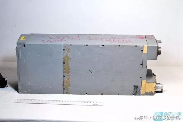 This side has some text, meaning that the machine is broken and can only be used as parts.
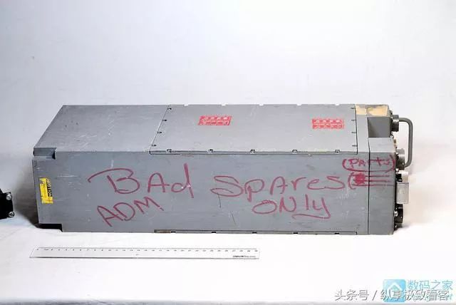 This side has two temperature-sensitive stickers, which I will introduce later.
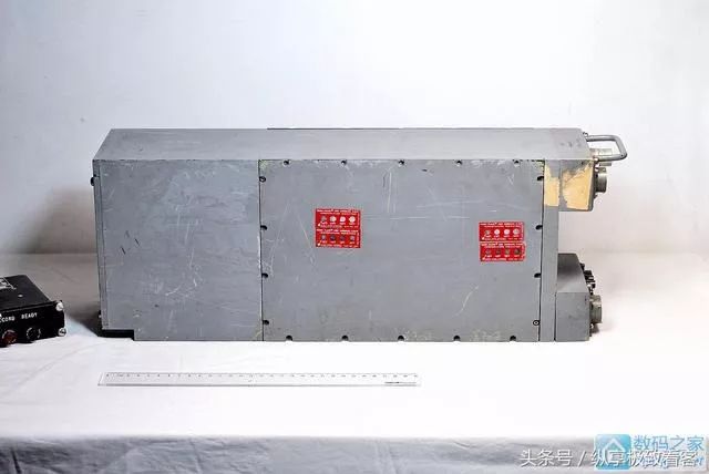 The seller also sent a small control box, but I don’t know if it is compatible with the machine.
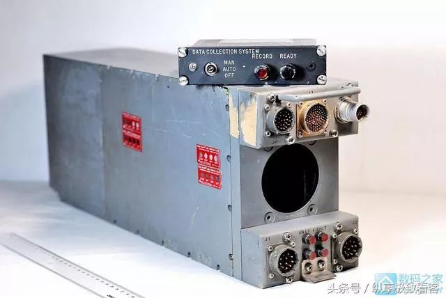 Number No.001, ASSY M600663-1
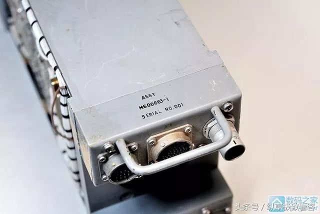 The interface part originally had a fan that has long been removed.
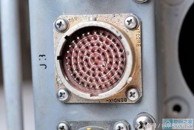
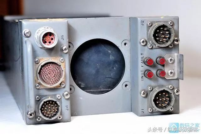 Aviation socket, which also has a coaxial interface, is also my first time seeing it.It is estimated that the simulated signal from the radar enters from here.
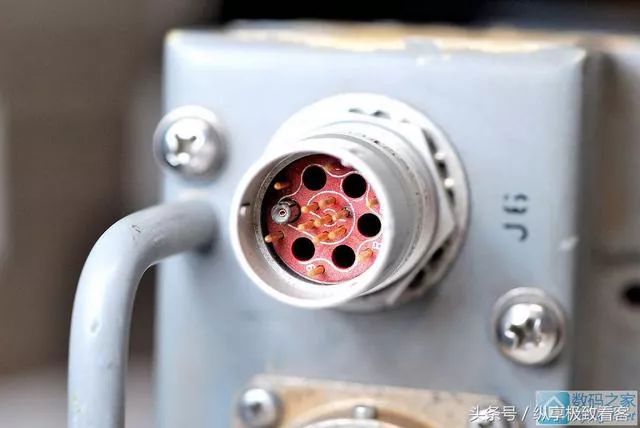 Giant aviation socket.
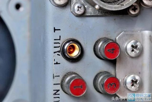
 Fault indicator light, which is gold-plated inside.
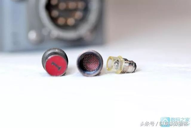
 The light bulb is an incandescent bulb, and there is a layer of steel mesh inside the lampshade.Indeed, high-end goods win in details.
 Below, this is the temperature indication label attached to the chassis, which can be used to detect the maximum temperature during the operation of the equipment.When the temperature exceeds the corresponding value on the label, the corresponding circle will turn black and will remain black and will not return.This way, after running the equipment on the plane for a period of time, you can know what the maximum temperature is when you return.
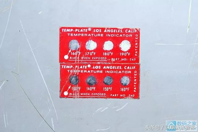 After blowing it with a hairdryer for a while, the 170-degree circle turned black.The machine’s rear, which hides a huge magnetic core storage module.
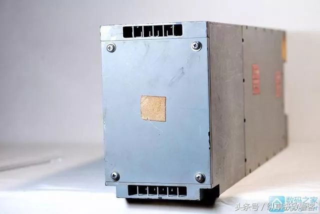 Next, open a side panel, and you can see the complex bus structure inside.………
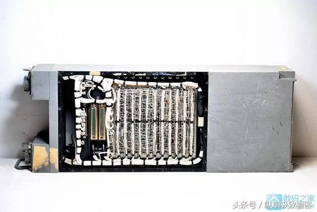
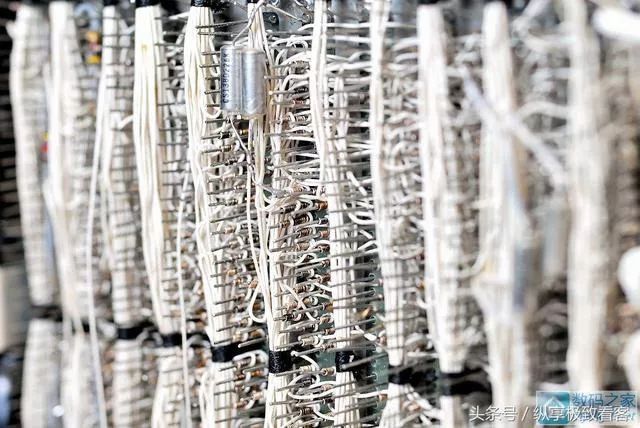
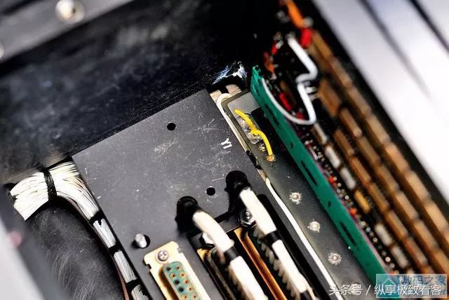
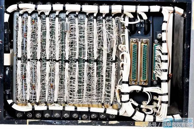 Up close, this is a circuit manually connected with a specialized winding tool.Since it does not require printed circuits, and is convenient for modification and prototype production, it is very common in early computers and military equipment.
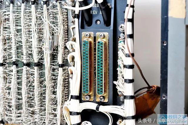
 These two interfaces may be used for debugging or programming (purely a guess).
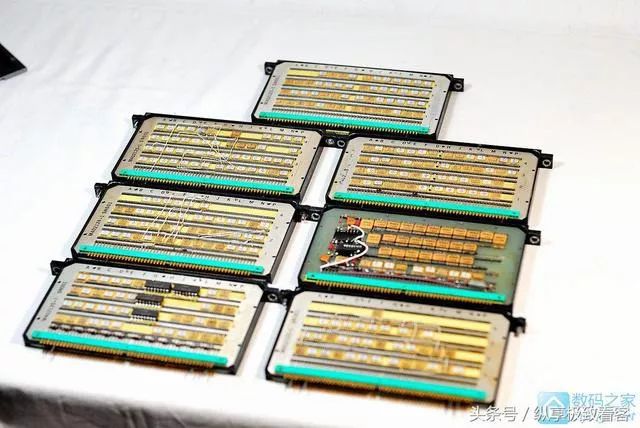
 Next, open the cover on the other side.……It turns out that many boards are missing inside, so it seems impossible to get the machine running again.However, fortunately, there are still 7 circuit boards left.
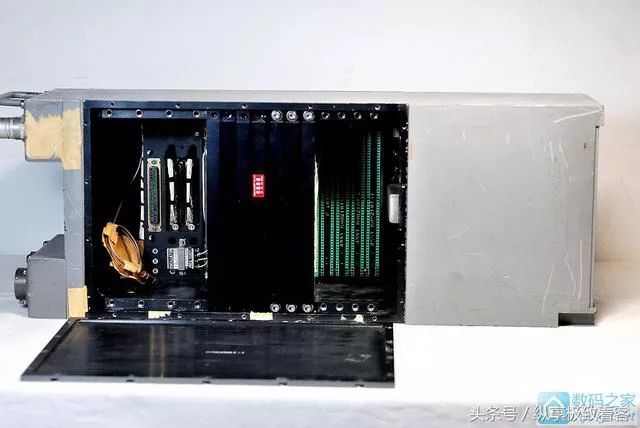 From the side, there are many chips on the circuit board.
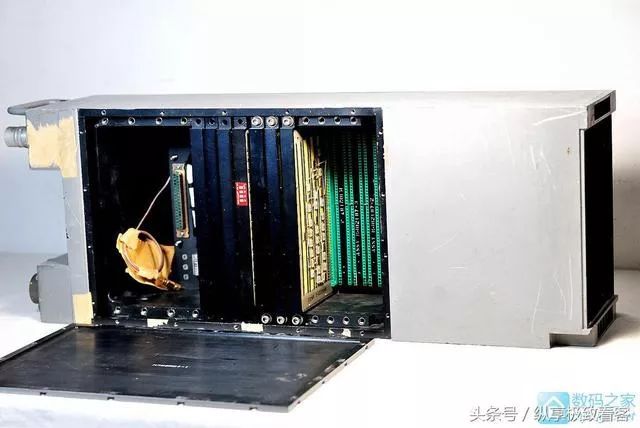 Change the angle.
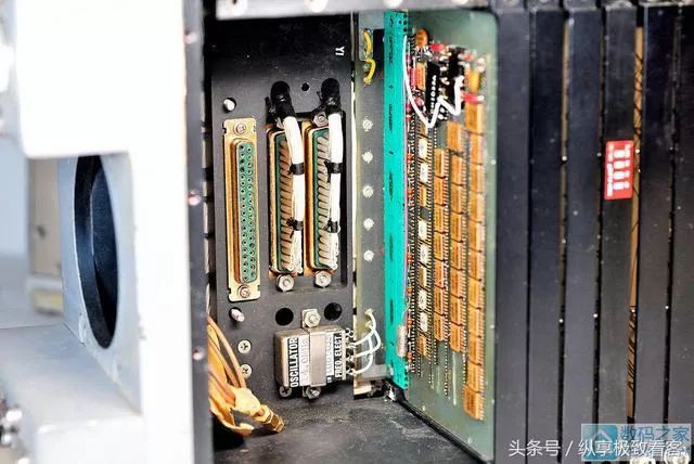 This has a 14MHz crystal oscillator, which seems to be active, providing the clock for the system.
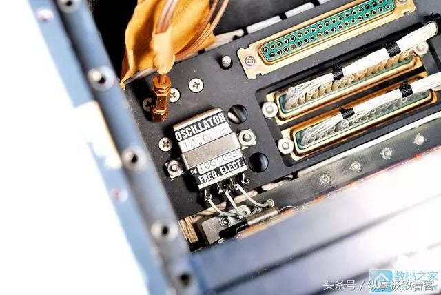 There is another one that has been disassembled.
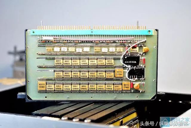
 Next, pull out the first board, it’s simply beautiful.It is hard to imagine that the Americans already had surface mount technology in 1968.At that time, Armstrong had not yet landed on the moon, and Dongfanghong had not yet gone to the sky. Most Chinese engineers had not even heard of integrated circuits.
 However, the reverse side.……Uh.
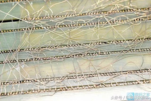
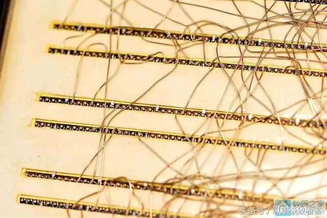
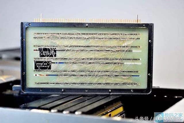 The wiring is too extravagant.……However, it should also be made as a prototype, just used to verify the function.The flying wires used here are also my first time seeing. It seems that the silver-plated wire is wrapped with a very thin layer of transparent insulating material, looking almost bare.
 The chip is manufactured by General Instruments, with an unknown purpose.It looks quite like a cache or something.This company was later acquired by Microchip (the company that makes PIC microcontrollers).
 The circuit board interface is also quite special, with hollow gold-plated cylinders.
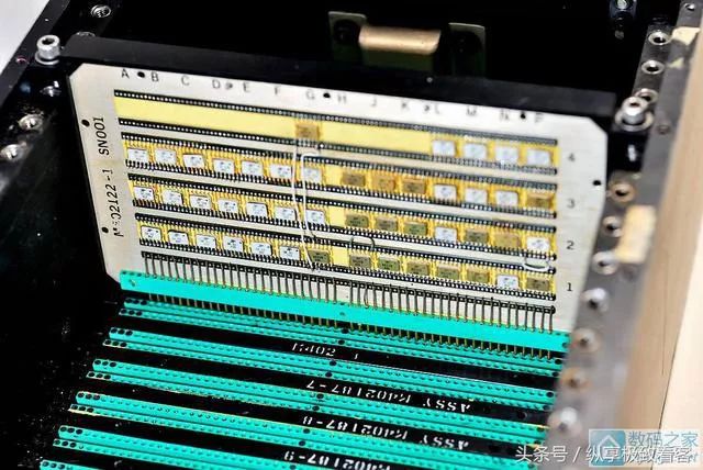
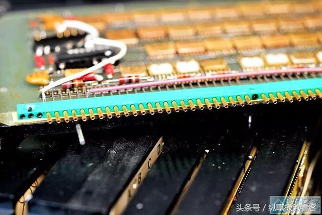 Next, take out the second board.The circuit board is completely made of stainless steel, embedded in an aluminum frame.This board is full of small-scale integrated circuits, which should be used to implement logic functions.
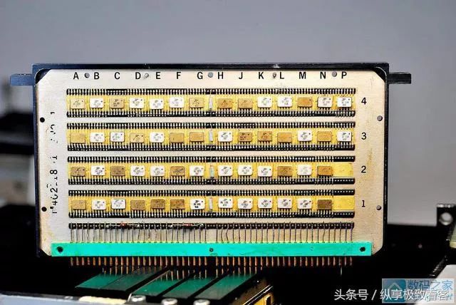 The reverse side is also the same extravagance.Upon closer inspection, it is found that the power and ground connections of each chip are connected to the power bus hidden inside the board, while the other pins use special silver-plated flying wires.
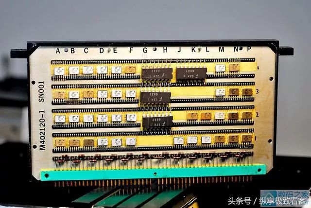
 The third board has several through-hole chips from Fairchild Semiconductor in addition to the surface mount chips.Of course, the model cannot be found anymore.
 This board has components on both sides.
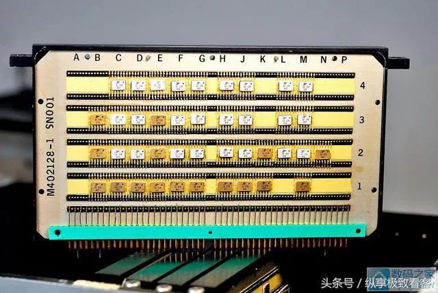 In fact, it is two stainless steel circuit boards embedded in the same aluminum frame on both sides.
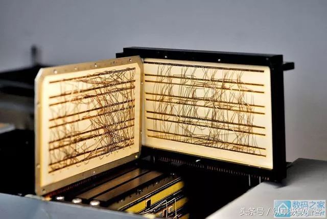 The circuit board number is also 001.
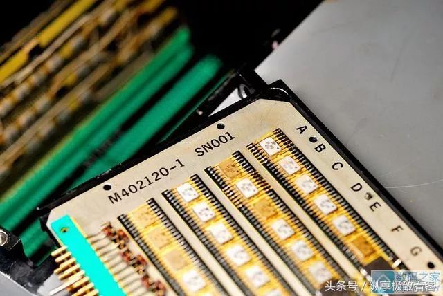 The other boards are actually very similar, all with many small-scale integrated circuits.This one is numbered 002.
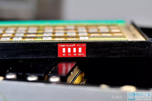
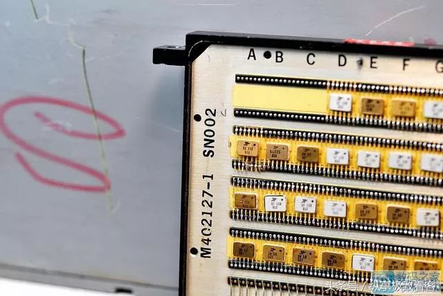 The board is also labeled with a temperature label, used to observe the internal temperature of the machine.
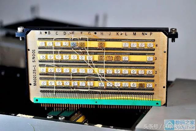
 This board obviously has a problem and has been manually wired for debugging.
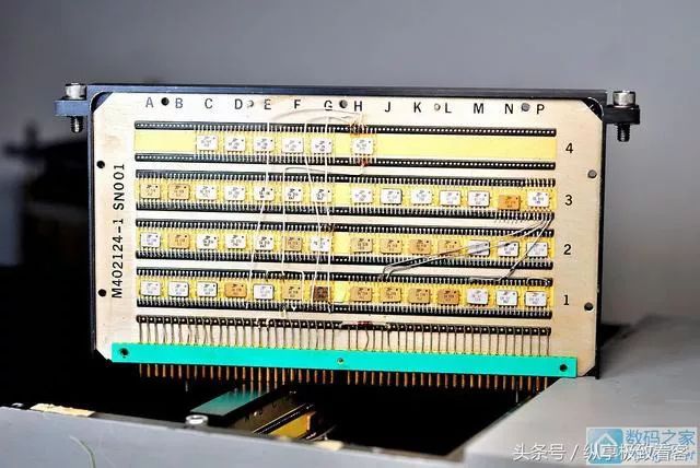
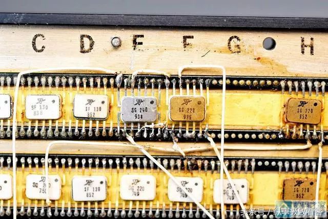 This one is the same.
 All remaining circuit boards have been taken out, and you can see that each board has different positioning pins at different positions to prevent incorrect slot insertion.
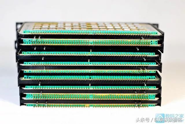 From the side.
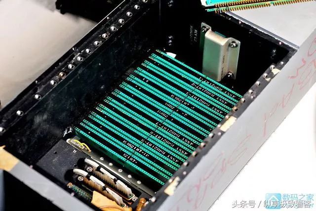
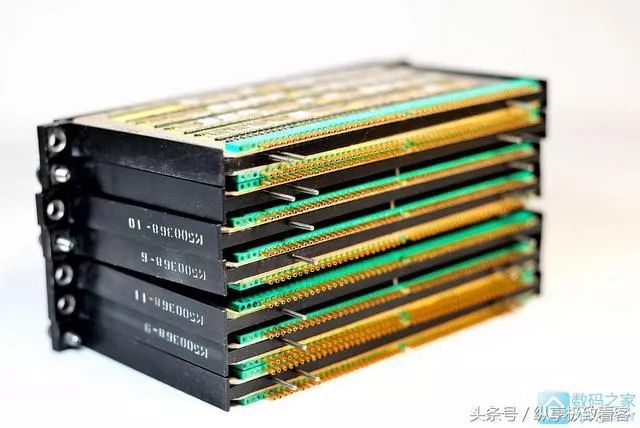 The empty chassis, with each socket labeled with the corresponding module number.
 All circuit boards together.
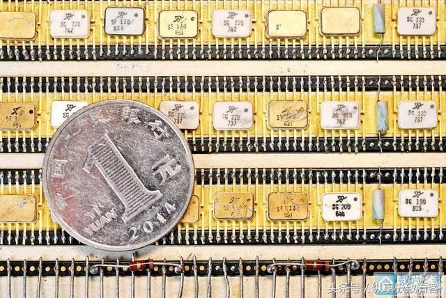
 Now let’s take a look at the details.The small-scale integrated circuits used on these circuit boards are produced by Sylvania (now the manufacturer of lights), which is one of the earliest manufacturers of integrated circuits. However, they fell behind later.………It must be mentioned that Sylvania successfully developed the TTL integrated circuit in 1963, making it the earliest manufacturer in the world to produce TTL integrated circuits (yes, earlier than the famous Texas Instruments and the 74 series chips).This machine uses Sylvania’s first generation of TTL integrated circuits.This miniaturized package is called flat pack, which was common in the 60s and widely used in military equipment.In the picture, SGxxx refers to logic gates, while SFxxx refers to flip-flops.According to the information, SG220 is a NAND gate, SG200 is an 8-input NAND gate, and SF130 is a 50MHz J-K flip-flop.
 There is nothing interesting inside the host. Next, let’s open the cover on the back of the machine to see what’s inside.
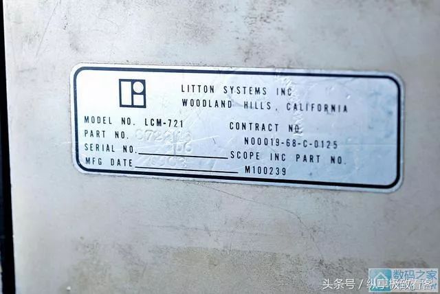
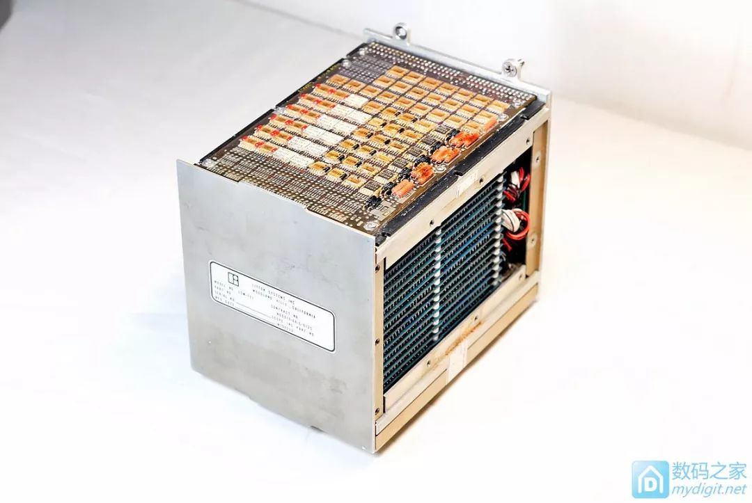
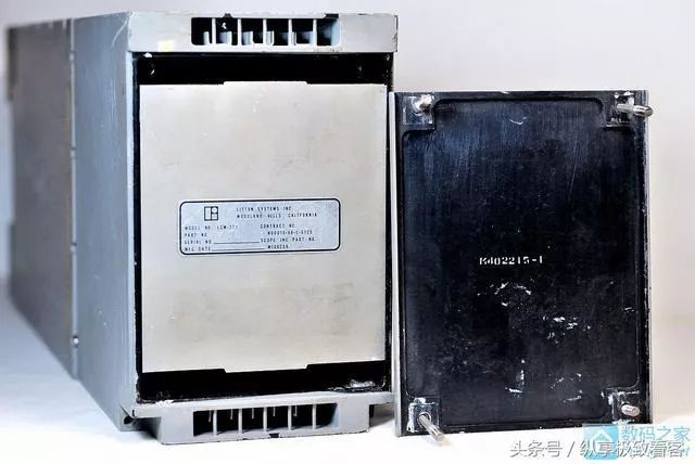 The nameplate states that this module is produced by Litton.This company is a well-known arms manufacturer in the United States, producing products including navigation systems, fire control systems, aerospace, and even spacesuits for NASA.The nameplate does not provide any valuable information, but according to information, this is a 32KB magnetic core storage module.
 Disassemble it.
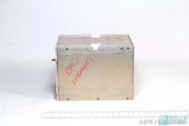
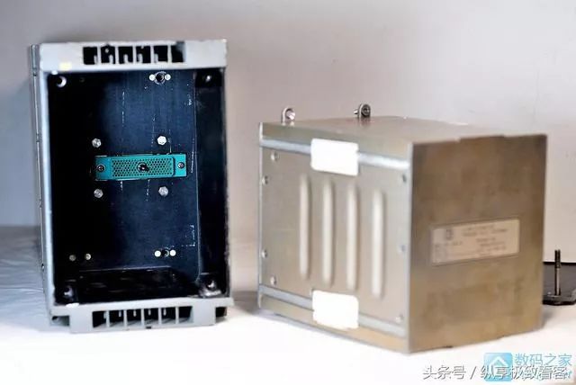 Looking closely, it says bad memory, indicating that the memory module is also broken.23333
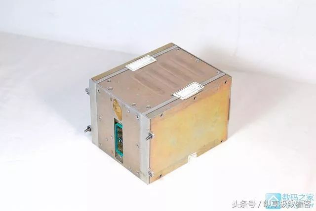
 The entire module is completely wrapped in metal and sealed.
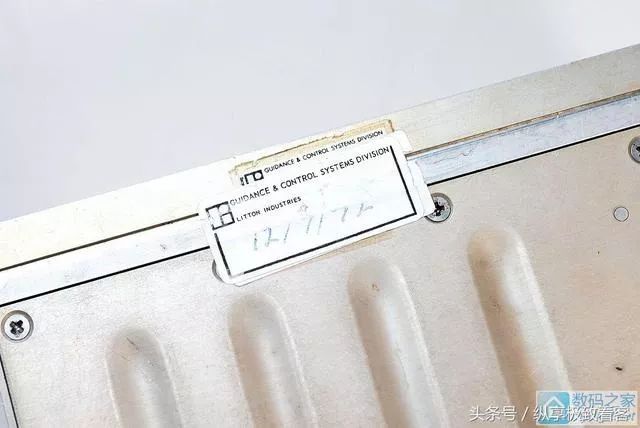
 The seal states Litton Company/Navigational and Control Division, with the last date being July 12, 1972.
 I didn’t want to break the seal, but to see what it looked like inside, I still had to take the painful step of disassembling it.……When the side is disassembled, a pile of magnetic core storage boards is seen stacked together.
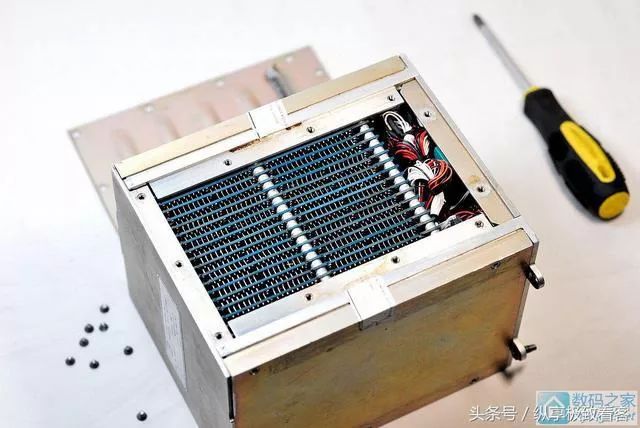 Change the angle.
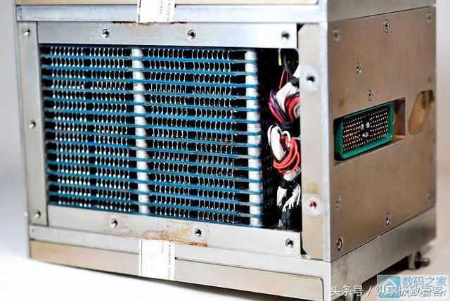 The cover on top should have something inside, so let’s continue disassembling.As soon as the cover is opened, a flash of gold passes by.……I am blinded.………
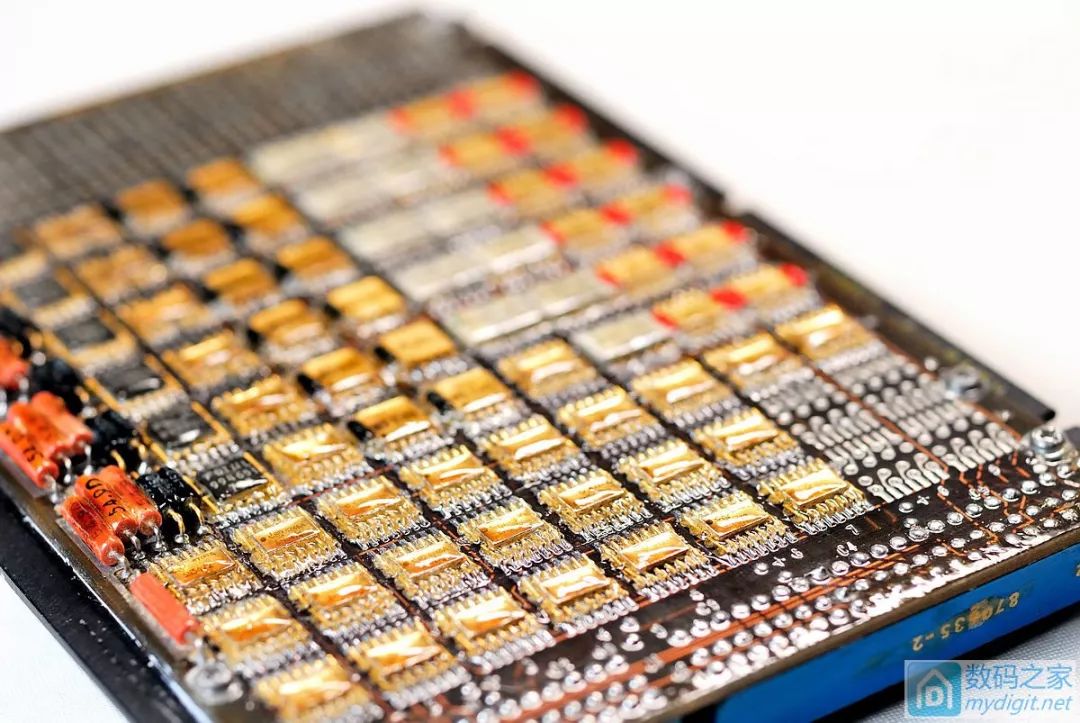
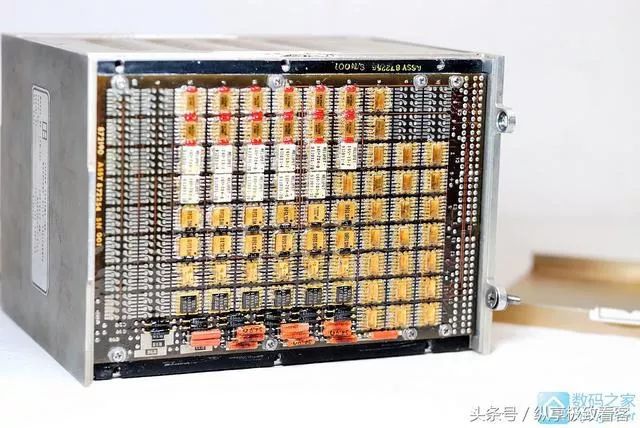 It is all golden chips, neatly arranged.………I must say, so far, this is the most beautiful circuit I have ever seen.
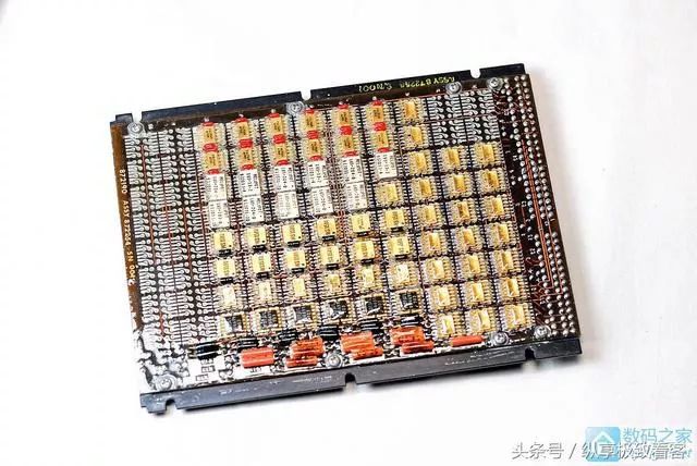 Taking it down, this is the front.
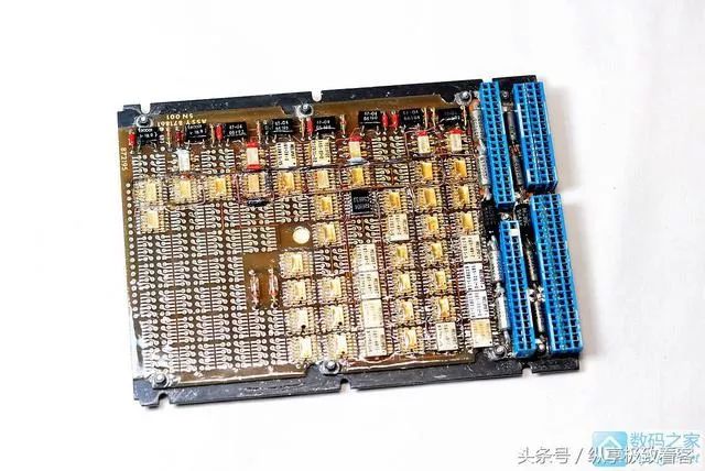 The reverse side has another layer, and the two boards are respectively attached to a steel plate on both sides.
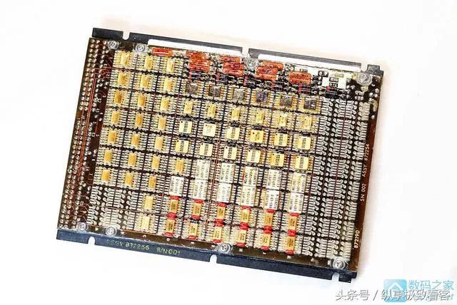 The front circuit board number 001.
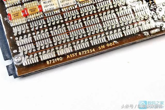 The chip from Fairchild.
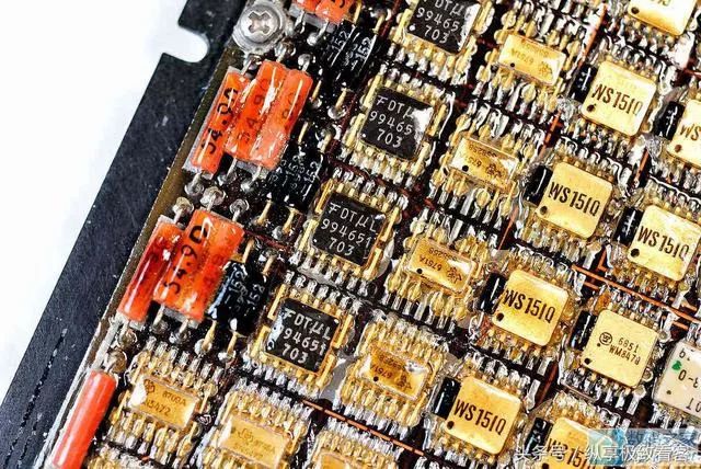 These are ceramic resistors.
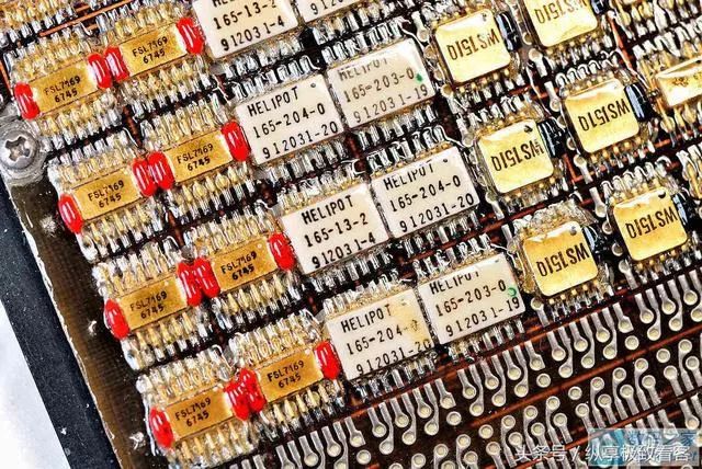 Resistors.
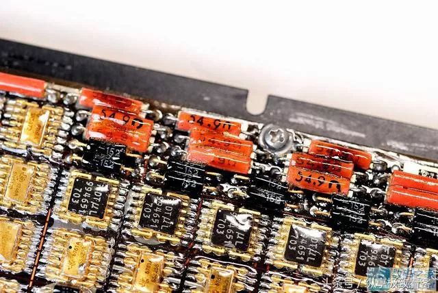 The white ones are Motorola chips.
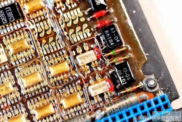 SN5400, the famous TI appears!This is a flat pack packaged 74 series TTL chip, produced in the 4th week of 1968.54 represents military-grade chips, and 5400 is naturally the famous 4-input NAND gate.It is said that in 1968, a chip like this was worth $20, so the entire system must have cost a lot.
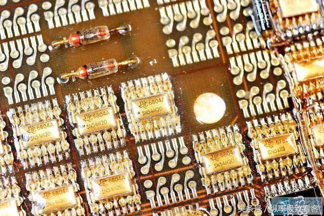 There is a similar circuit board on the other side of the module.The front looks exactly the same, probably the front-end circuit for reading and writing the magnetic core.
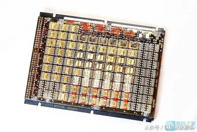 The flying wires are still unavoidable.
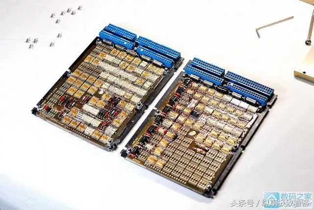
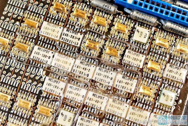 Two boards together, this is the reverse side, with different functions and different component layouts.
 The front side seems the same.
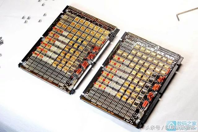 Let’s take a look at the serial number, one is 01, the other is 02.The serial numbers are printed on, and the Americans really put in a lot of thought.……
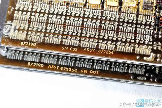 Close-up, modern 74HC chips and 50-year-old 54 chips appearing together.It is found that although so much time has passed, the pitch of the SO package has not changed at all from 50 years ago.I can’t help but admire the foresight of the Americans when they set standards.And look at us, many standards are changed frequently, making them difficult to continue.
 After removing the board, the module is made of stainless steel.Gold-plated interfaces.
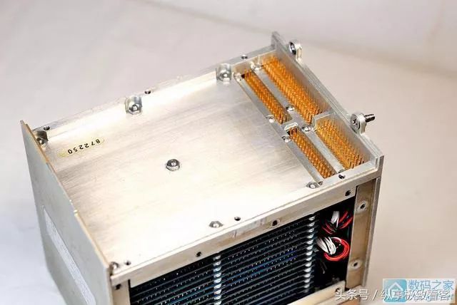 Disassemble it further, and you can see the magnetic core storage piled up.
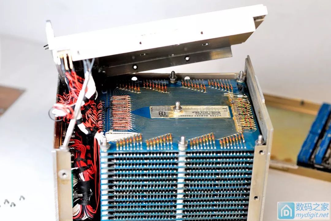 The top is a diode board, and the ones below are magnetic core boards.Unfortunately, they are soldered together and cannot be disassembled without damage, so I won’t disassemble them.Diode array.A pile of wiring.
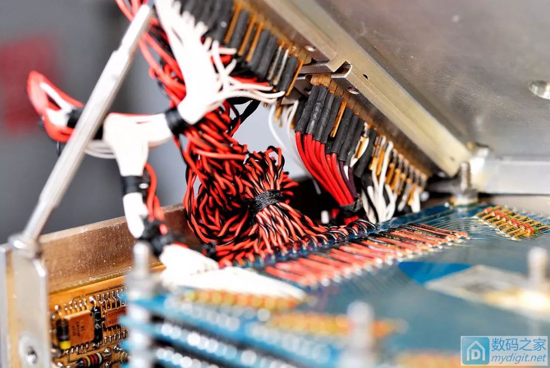 Here is a small board, and the chips on it are simply amazing.……From left to right, they come from National Semiconductor (NS), Texas Instruments (TI), Motorola, HELIPOT (a resistor manufacturer), and the last one is Fairchild.Finally, here are a few pictures of the module in full view.Because it is so beautiful, I can’t help but post a few more pictures.
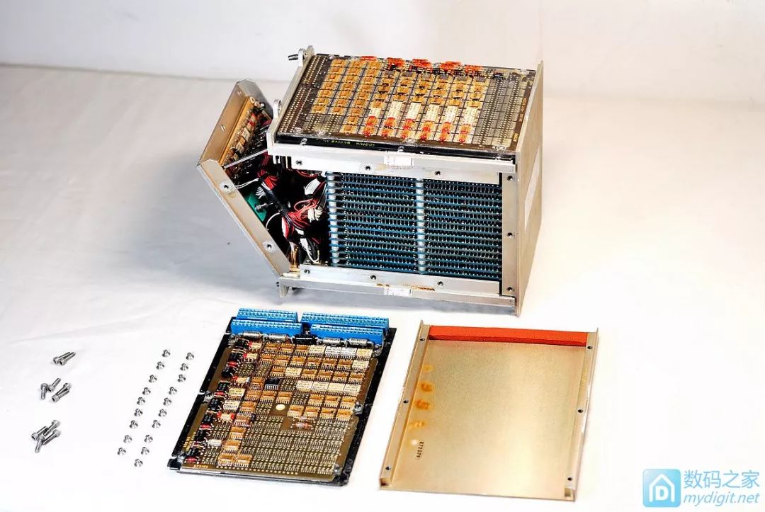
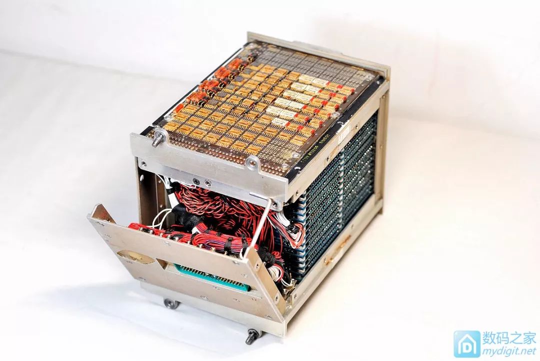
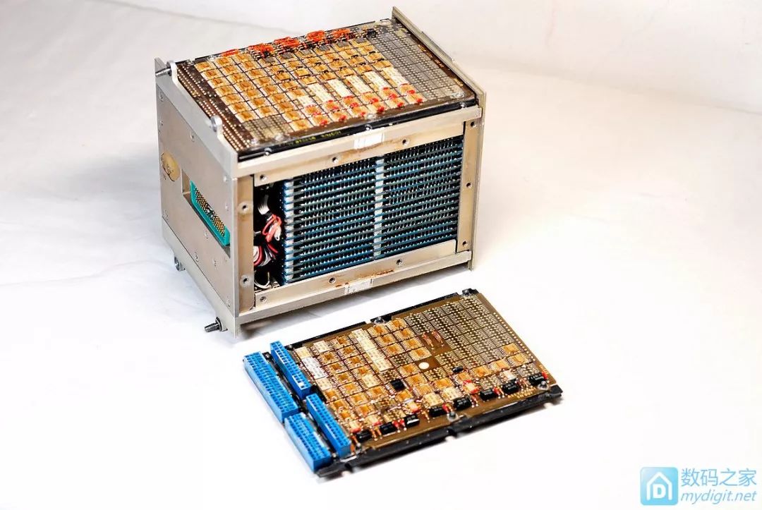
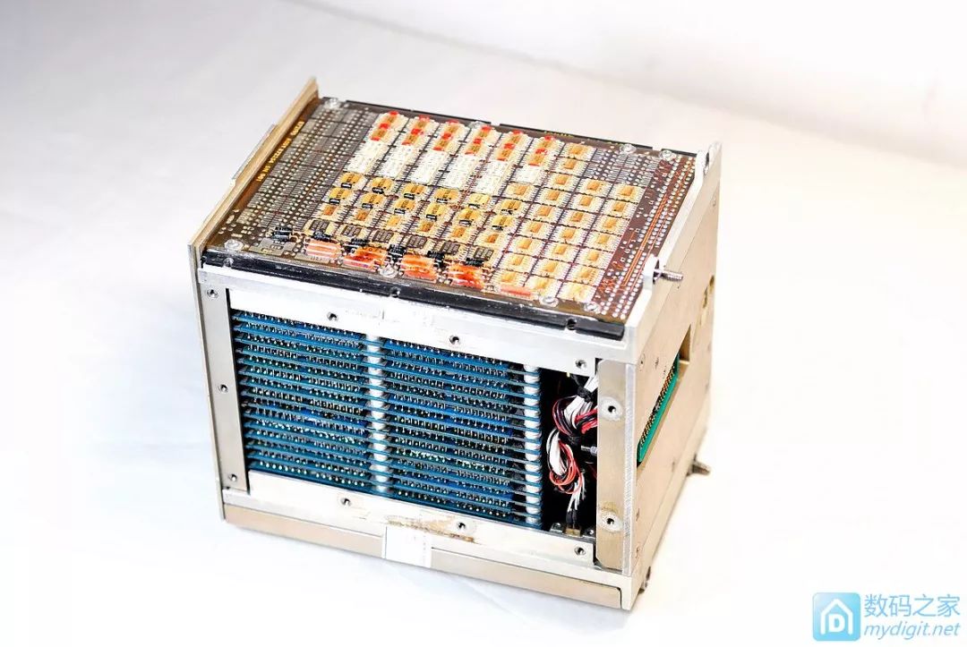
 The disassembly is complete.Finally, here is a picture that can serve as a desktop background.
 [End, thank you for watching~]
Reprinted from Digital Home avatar. If there is any infringement, please contact the author for deletion!Thank you!
Link: http://bbs.eeworld.com.cn/thread-527890-1-1.html