1.System Functions
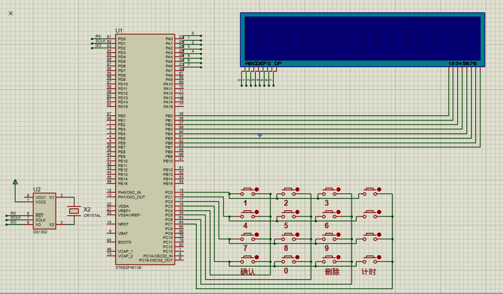
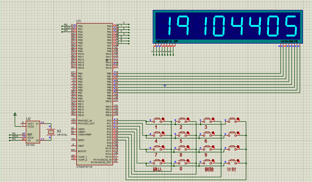
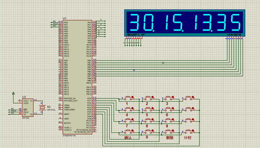
In the STM32 main control system, we implemented a 4×4 keyboard matrix interface for convenient input of student ID numbers. Users only need to press the corresponding number key, and the LCD1602 LCD screen will immediately display the entered value. Once the user enters a continuous sequence of 8 digits, pressing the “Confirm” key will lock the entered student ID on the screen for subsequent operations and confirmations. In addition, the system also incorporates a practical “Timing” function. When the user presses the “Timing” button, the system quickly captures the current time information and displays it on the LCD1602 screen, providing users with instant time reference. Of course, considering that users may need to re-enter the student ID, we have also specially designed a “Delete” button. Users just need to press this button lightly, and the current student ID on the screen will be cleared, allowing users to input a new student ID through the 4×4 keyboard matrix again. The entire system not only provides a smooth number input and confirmation function but also has convenient time display and student ID reset capabilities, bringing great convenience to users.
2.System Design Principles
The matrix keyboard is an input device based on the principle of row-column intersection detection. It utilizes a multi-row and multi-column key layout, with each key located at the intersection of a row and a column. In the initial state, all row and column lines maintain a high level. When a user presses a key, that key connects its corresponding row and column, causing the level of that row to drop while the corresponding column’s level rises.
The scanning process of the matrix keyboard is roughly as follows:
Initialization: First, the system sets all row lines to high level and configures all column lines to input mode to monitor level changes.
Row Scanning: The system then begins scanning row by row, setting one row to low level while keeping other rows at high level.
Column Detection: When a certain row is set to low level, the system checks the level status of all column lines. If it detects that a column line has changed from high to low level, it indicates that the key at the intersection of that row and column has been pressed.
Recording Information: Once a key press is detected, the system records the information of that row and column and resets that row to high level to proceed with scanning the next row.
Repeating Scanning: This process repeats until all rows have been scanned.
Key Recognition: By analyzing which rows and columns are activated, the system can determine which specific key has been pressed and convert it into the corresponding key code for further processing by the system.
DS1302 real-time clock module works based on its clock counting and data storage functions. This module generates stable clock pulse signals through an external crystal oscillator, which are processed by internal circuits to form counting signals of different frequencies, used for real-time updates of clock/calendar register values.
In terms of data storage, the DS1302 internally integrates RAM for storing current year, month, day, hour, minute, second, and other time information. Through a complex control logic, the DS1302 can perform read and write operations on this data, ensuring accurate recording and reading of time.
In summary, the DS1302 real-time clock module generates stable clock signals through an external crystal oscillator and updates clock/calendar information through division and counting processing, and then stores this information in internalRAM, providing reliable real-time time services to users.
The digital tube is a commonly used electronic display device that displays numbers or characters through an internal LED (light-emitting diode) array. These LEDs are arranged in a specific pattern, with each LED segment representing a specific part of a number or character (such as a, b, c, d, e, f, g). There are two common connection methods for digital tubes: common cathode and common anode, which determine the lighting method of the LEDs.
To display specific numbers or characters, each LED segment of the digital tube (a to g) can be controlled individually. For example, to display the number “2”, the control system will activate a, b, c, d, e these five LED segments and turn off f and g segments. By precisely controlling the on-off combinations of these LED segments, the digital tube can clearly display numbers from 0 to 9 as well as certain specific characters or symbols. This flexible control method makes digital tubes widely used in various electronic devices.
3.
4.
// Time display if(time==1){ for(j=0;j<8;j++){ GPIOB->ODR=0x0001<<j;// Choose which digital tube to display switch(j){ case 0:GPIOA->ODR=number[day/10];break; case 1:GPIOA->ODR=number2[day%10];break; case 2:GPIOA->ODR=number[shi/10];break; case 3:GPIOA->ODR=number2[shi%10];break; case 4:GPIOA->ODR=number[fen/10];break; case 5:GPIOA->ODR=number2[fen%10];break; case 6:GPIOA->ODR=number[miao/10];break; case 7:GPIOA->ODR=number[miao%10];break; } HAL_Delay(1); } } else{// Display digital tube Numbertwo=Number; for(j=0;j<show_set;j++){ GPIOB->ODR=(0x0080>>(8-show_set))>>j;// Choose which digital tube to display GPIOA->ODR=number[Numbertwo%10];// Digital tube pins Numbertwo=Numbertwo/10; HAL_Delay(1); } }5.
If you need custom Proteus simulation, go to the idle fish search: Amphibious Electronics. The above simulation program documentation can also be found there, with various templates and custom simulation designs available: