Project Overview
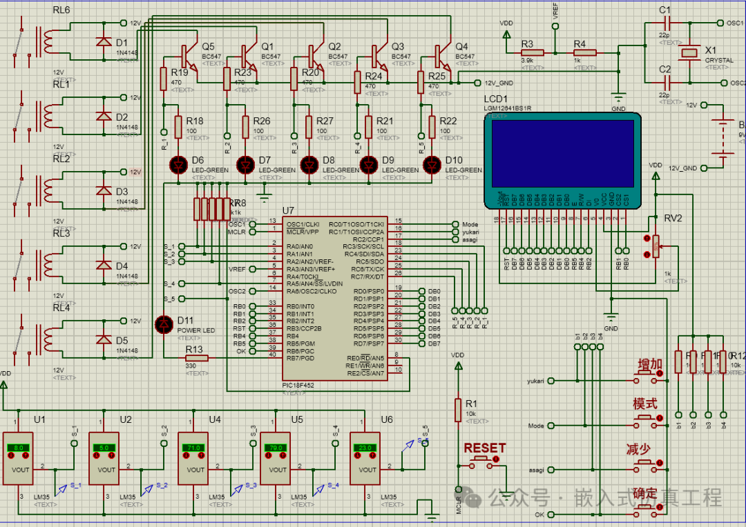
This project aims to design a temperature control system based on the PIC18F452 microcontroller, programmed using the CCS C compiler. The system collects temperature data through five LM35 temperature sensors and sets the temperature range using four buttons. When the temperature exceeds the set range, the relay outputs a control signal to drive the LGM12641BS1R LCD display, showing the set temperature interface and the relay output status. The entire system will be simulated in Proteus.
Hardware Design
-
Microcontroller: PIC18F452
-
Temperature Sensors: LM35 (5 units)
-
Buttons: 4 (for setting the temperature range)
-
Relays: 5 (for controlling output)
-
LCD Display: LGM12641BS1R
-
Others: Resistors, capacitors, crystal oscillators, etc.
Software Design
-
Development Environment: CCS C Compiler
-
Main Functions:
-
Read data from LM35 temperature sensors
-
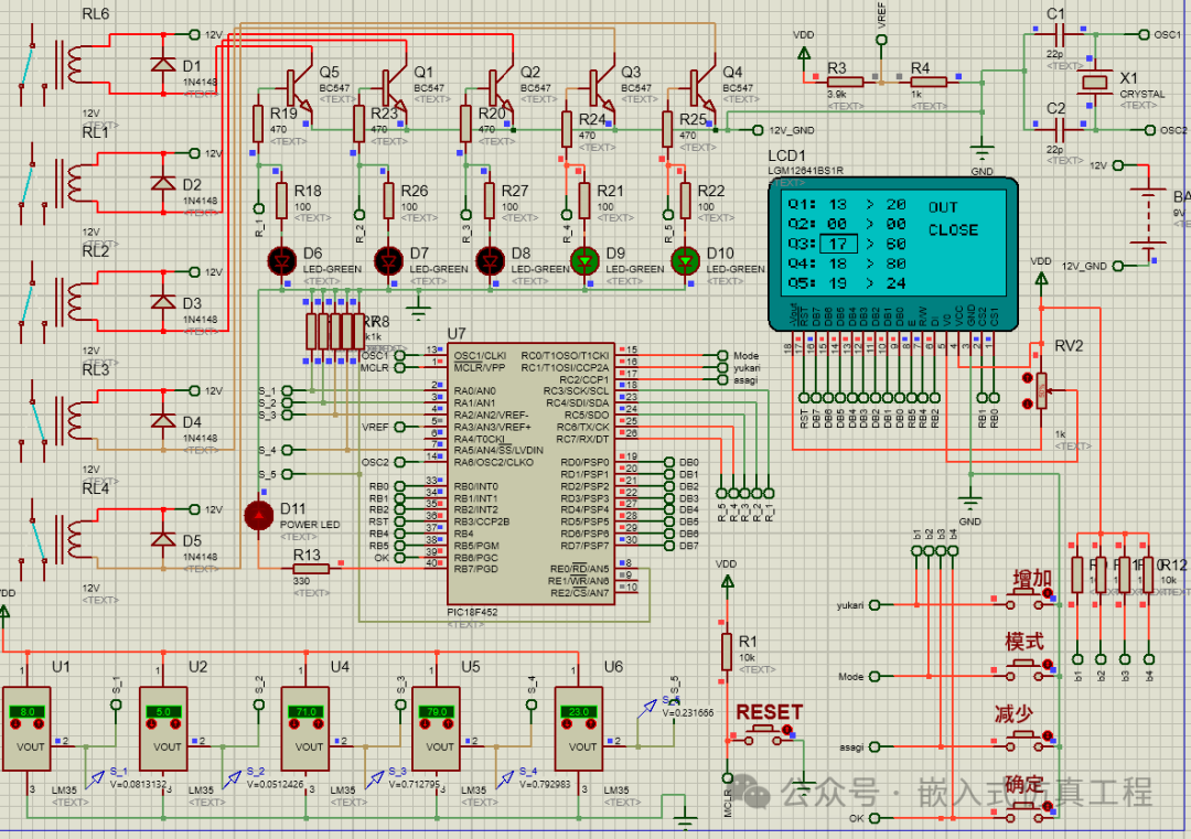
Set temperature range using buttons
-
Control relay output
-
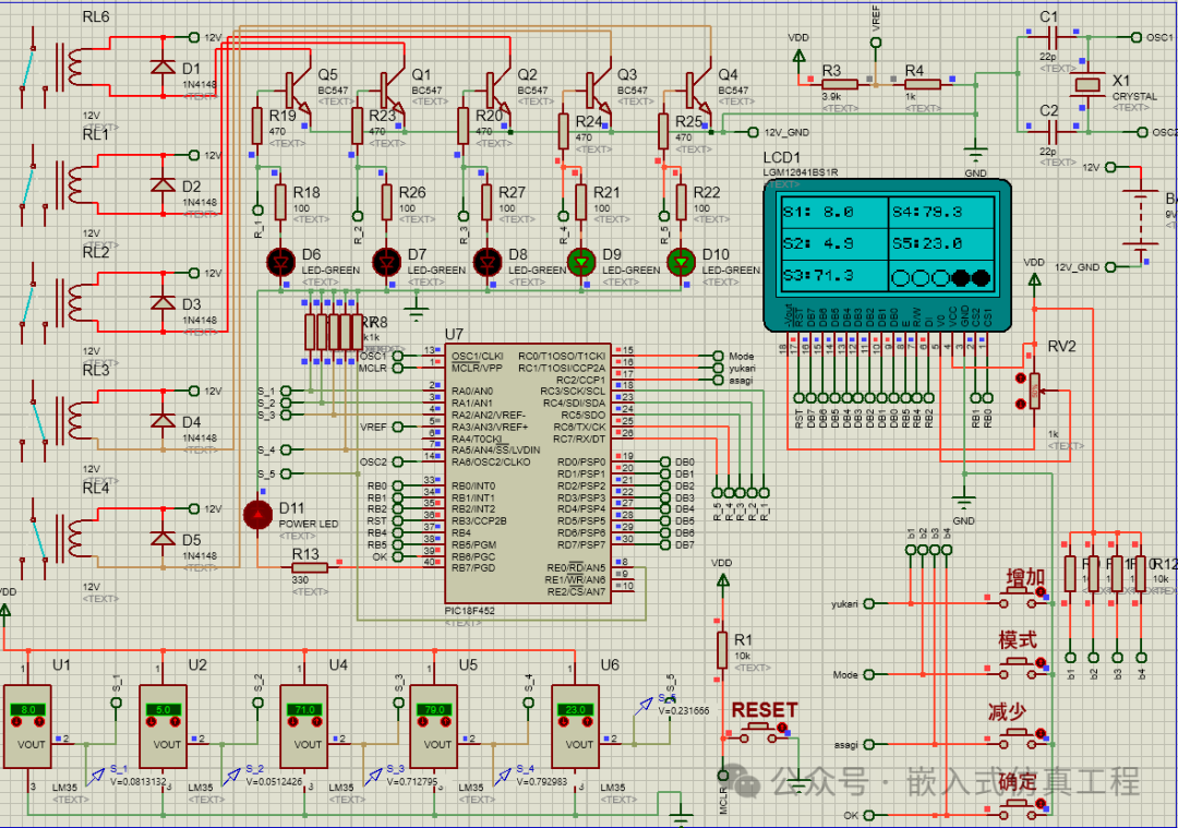
Display the set temperature interface and relay output status on LGM12641BS1R
Partial Code Implementation
void eeprom_finish(){
a_s1=read_eeprom(0);
delay_us(50);
u_s1=read_eeprom(5);
delay_us(50);
a_s2=read_eeprom(10);
delay_us(50);
u_s2=read_eeprom(15);
delay_us(50);
a_s3=read_eeprom(20);
delay_us(50);
u_s3=read_eeprom(25);
delay_us(50);
a_s4=read_eeprom(30);
delay_us(50);
u_s4=read_eeprom(35);
delay_us(50);
a_s5=read_eeprom(40);
delay_us(50);
u_s5=read_eeprom(45);
}
void tab_inlay(){
switch(tab){
case 1:
glcd_rect(80,16,120,30,no,off);
glcd_rect(20,0,42,12,no,on);
break;
case 2:
glcd_rect(20,0,42,12,no,off);
glcd_rect(54,0,76,12,no,on);
break;
case 3:
glcd_rect(54,0,76,12,no,off);
glcd_rect(20,13,42,25,no,on);
break;
case 4:
glcd_rect(20,13,42,25,no,off);
glcd_rect(54,13,76,25,no,on);
break;
case 5:
glcd_rect(54,13,76,25,no,off);
glcd_rect(20,26,42,38,no,on);
break;
case 6:
glcd_rect(20,26,42,38,no,off);
glcd_rect(54,26,76,38,no,on);
break;
case 7:
glcd_rect(54,26,76,38,no,off);
glcd_rect(20,39,42,51,no,on);
break;
case 8:
glcd_rect(20,39,42,51,no,off);
glcd_rect(54,39,76,51,no,on);
break;
case 9:
glcd_rect(54,39,76,51,no,off);
glcd_rect(20,52,42,63,no,on);
break;
case 10:
glcd_rect(20,52,42,63,no,off);
glcd_rect(54,52,76,63,no,on);
break;
case 11:
glcd_rect(54,52,76,63,no,off);
glcd_rect(80,1,125,15,no,on);
break;
case 12:
glcd_rect(80,1,125,15,no,off);
glcd_rect(80,16,120,30,no,on);
break;
}
}
Proteus Simulation
-
Create Circuit Diagram: Create a circuit diagram in Proteus, including components such as PIC18F452, LM35, buttons, relays, LGM12641BS1R, etc.
-
Load Program: Load the compiled HEX file into the PIC18F452.
-
Run Simulation: Run the simulation, adjust the LM35 to set temperature data, and observe the content displayed on the LGM12641BS1R and the changes in relay status.
Conclusion
This project implements the basic functions of a temperature control system using the PIC18F452 microcontroller, including temperature acquisition, button settings, relay control, and LCD display. Through Proteus simulation, the correctness and stability of the system can be verified. In practical applications, further optimization of the code and hardware design may be needed to improve the system’s reliability and accuracy.
Welcome to follow (operation reference article:Follow the public account and send message operation), click the blue text at the top “Embedded Simulation Project” or long press to identify the QR code to follow
Reply in the public account
1803
After receiving, automatically send the CCS project link for this project