(1) AVR Microcontroller Simulation Example
This example implements AVR driving LCD1602 and uses an oscilloscope to monitor the data line.
Before starting, prepare the simulation file, which is the debug or download file generated by the compiler. Different compilers produce different file formats, such as ICC produces COF, IAR produces D90, and GCC produces COF and ELF. Proteus 6.7sp3 supports COF, D90, HEX, etc., but does not support ELF yet.
This example uses: lcd_C.hex.
Let’s get started!!!!!!!
Run Proteus 6 Professional (ISIS 6 Professional), and the following window will appear:
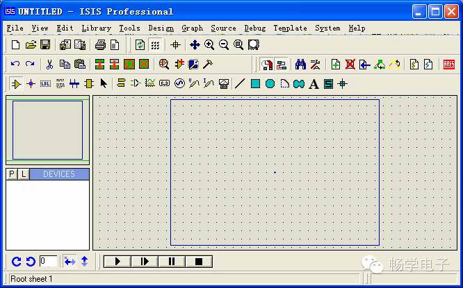
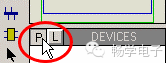
1. Add components to the component list: The components needed for this example are: ATMEGA16, LM016L (LCD1602), GND, and oscilloscope. Click the “P” button to open the component selection dialog.
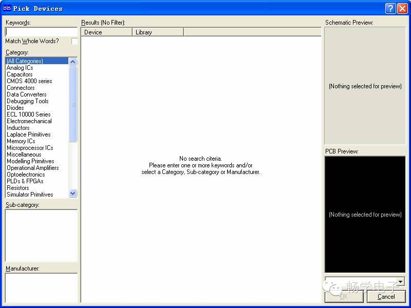
In the dialog’s KEYWORDS field, enter ATMEGA16, and you will get the following results:
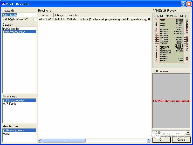
Click OK to close the dialog, and ATMEGA16 will be listed in the component list. Similarly, find LM016L.
Final result:
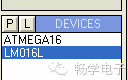
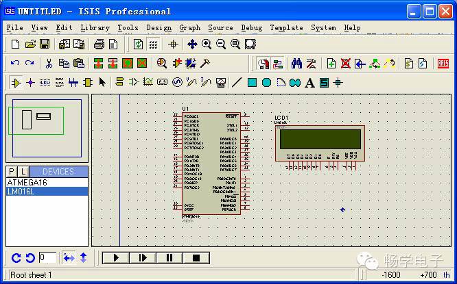
2. Place components: Select ATMEGA16 from the component list with the left mouse button, and click the left mouse button in the schematic editor window to place ATMEGA16 there. Similarly, place LM016L.
Add “GND”: Select the model selection toolbar icon , and you will see:
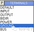
Select GROUND with the left mouse button and click in the schematic editor window to place “GND” there. To add the oscilloscope: Select the model selection toolbar icon
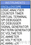
and select OSCILLOSCOPE with the left mouse button to place the oscilloscope in the schematic editor window.
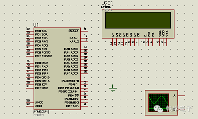
Note: When placing components, ensure that they are placed within the blue box. If accidentally placed outside, you will not be able to use the mouse outside, and you need to use the menu “Edit”‘s “Tidy” to clear them. The method is simple; just click “Tidy”. During operation, you may need to move parts of the circuit as a whole; to do this, first drag select with the right mouse button, and then click to move that part of the circuit with the mouse. Click the left mouse button at the target position to place that part of the circuit there.
3. Wiring
AVR, LCD’s VSS, VDD, VEE do not need to be connected, default VSS=0V, VDD=5V, VEE=-5V, GND=0V
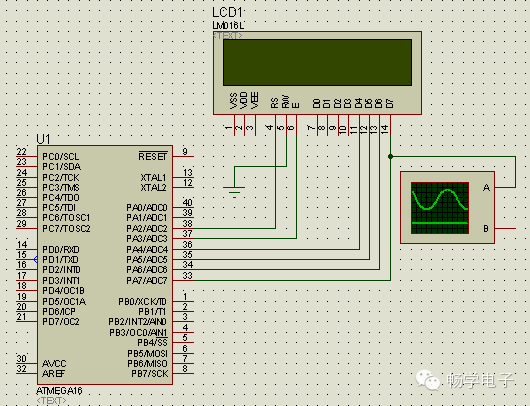
4. Add simulation file
Right-click ATMEGA16 and then left-click to bring up
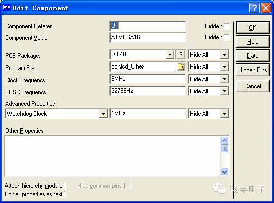
In the Program File, click to open the file browser dialog, find the lcd_C.hex file, click OK to complete adding the file, set the Clock Frequency to 8MHz, and click OK to exit.
5. Simulation
Click to start the simulation.

Note: The red color represents high level, blue represents low level, and gray represents uncertain level (floating). While running, you can check the AVR’s relevant resources in the Debug menu.
6. Source Code Debugging
First, I declare that I am using ICC, version ICC6.31a Pro. Proteus supports COF file debugging. When using ICC, you should change the compiler option, set AVRStudioVersion to Studio3.x, so you can see the original code in Proteus.
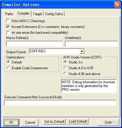
In Proteus, after completing the schematic drawing and adding the debug file (COF file), click to open the AVR Source Code window. If it does not appear in debug mode, please check in the Debug menu.
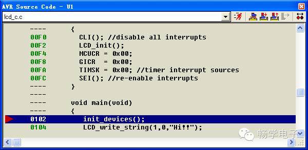
Let me explain , I will describe the following:
1* Continuous run will exit the single-step debugging state and close the AVR Source Code window.
2* Single-step run will skip over sub-functions.
3* Single-step run will enter into sub-functions.
4* Exit the current function; when you enter a function using 3*, using this will immediately exit that function and return to the previous function. It should be used in conjunction with 3*.
5* Run to the line where the mouse is located.
6* Add or remove breakpoints; after setting a breakpoint, the program will stop at that breakpoint.
Additionally, you can right-click in the AVR Source Code window to bring up a right-click menu. The functions above will not be explained here.