When wiring in industrial settings, the 9-pin interface of the PROFIBUS connector is a familiar sight for engineers—pins 3 and 8 are responsible for data transmission, which is common knowledge. But have you noticed that pins 2 and 7 are labeled for 24V power output? What are they used for? This easily overlooked detail is crucial for the normal operation of many programming devices.

The Core Function of Pins 2 and 7:
Power Supply for Programming Devices
Pins 2 and 7 of the PROFIBUS connector essentially serve as a set of 24V power output interfaces, specifically designed for programming devices that require external power. The most typical scenario is the early RS232 interface PC adapters:
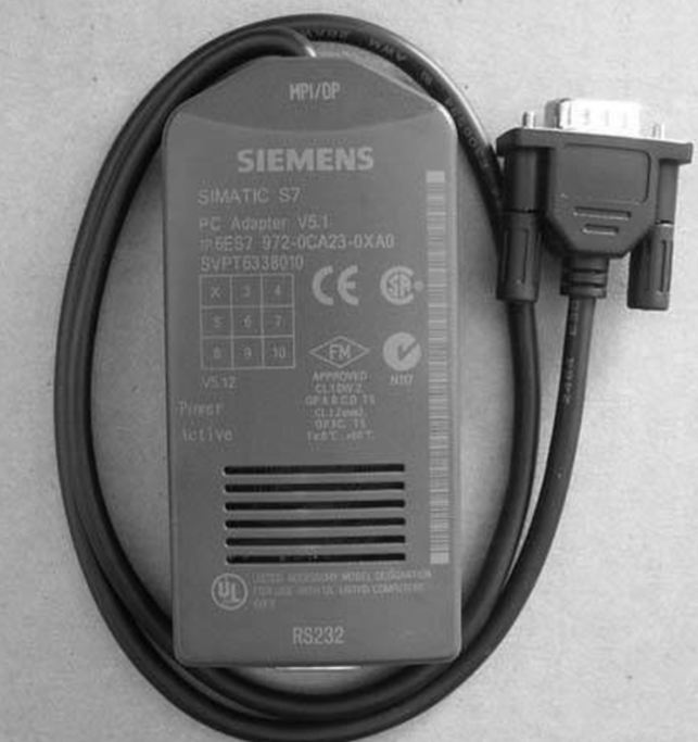
These adapters require a 24V power supply to operate, but the connected PC cannot provide power, so they must draw power through the PROFIBUS interface—when the adapter is plugged into the PROFIBUS socket, the 24V power from pins 2 and 7 powers it, and once the power indicator lights up, normal communication can occur.
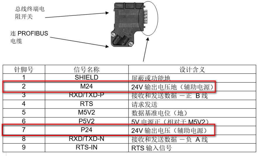
Why Does the Programming Device Fail to Power On When Plugged into the Slave Interface?
Many engineers have encountered the issue of plugging a PC adapter into the programming port of a PROFIBUS slave device, only to find that the device does not start. The core reason lies in the power supply logic:
-
The master device (such as a PLC master) typically has a 24V output capability, supplying power to the programming device through pins 2 and 7;
-
The slave device (such as a remote I/O module) does not provide a 24V power supply, and the PROFIBUS cable only transmits data through pins 3 and 8, unable to conduct power, thus the slave interface cannot power the PC adapter.
In addition to RS232 interface PC adapters, the power supply methods for common PROFIBUS programming devices vary, directly affecting their use in the field:
|
Device Type |
Power Supply Method |
Applicable Scenarios |
|
RS232 Interface PC Adapter |
Relies on PROFIBUS pins 2/7 for 24V power supply |
Only master interface |
|
CP5511/12, CP5611/12/13 |
Driven directly by the PC (no external power required) |
Applicable to both master and slave interfaces |
|
USB Interface PC Adapter |
Requires only 5V power (drawn from USB) |
Applicable to both master and slave interfaces |
|
S7-1500 Ethernet Programming |
Powered via Ethernet (PoE or standalone power) |
No dedicated programming converter required |
Understanding the power supply logic of pins 2 and 7 can help avoid two common issues:
-
When using an RS232 interface PC adapter, be sure to plug it into the master interface (such as the PROFIBUS port of the PLC) to avoid “no power” issues at the slave interface that lead to communication failures;
-
When selecting programming devices, choose based on the type of field interface (master/slave) and power supply conditions: prioritize USB adapters or CP series cards for slave interfaces to reduce wiring limitations.
What “stuck” issues have you encountered while wiring PROFIBUS? For example, insufficient power supply at the interface or communication interruptions, share your solutions in the comments.

If you want to learn more, check out the popular courses on the 1847 Industrial Learning Platform that many are studying!
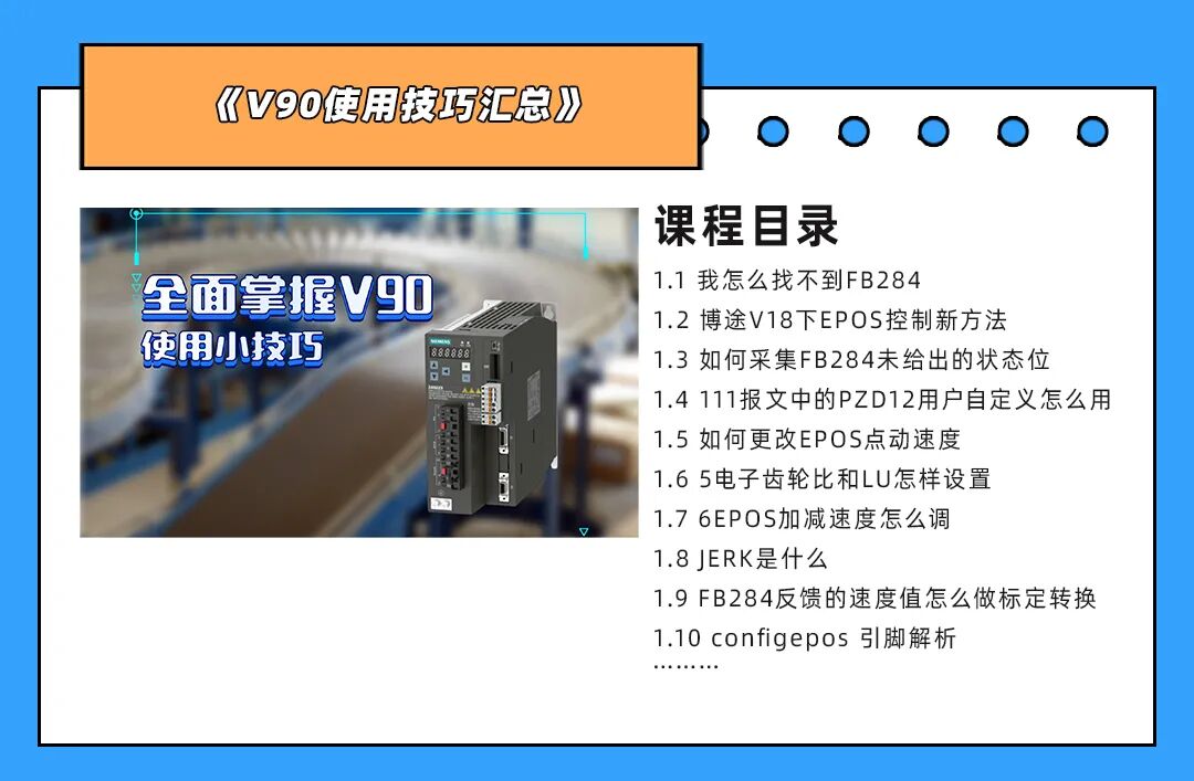
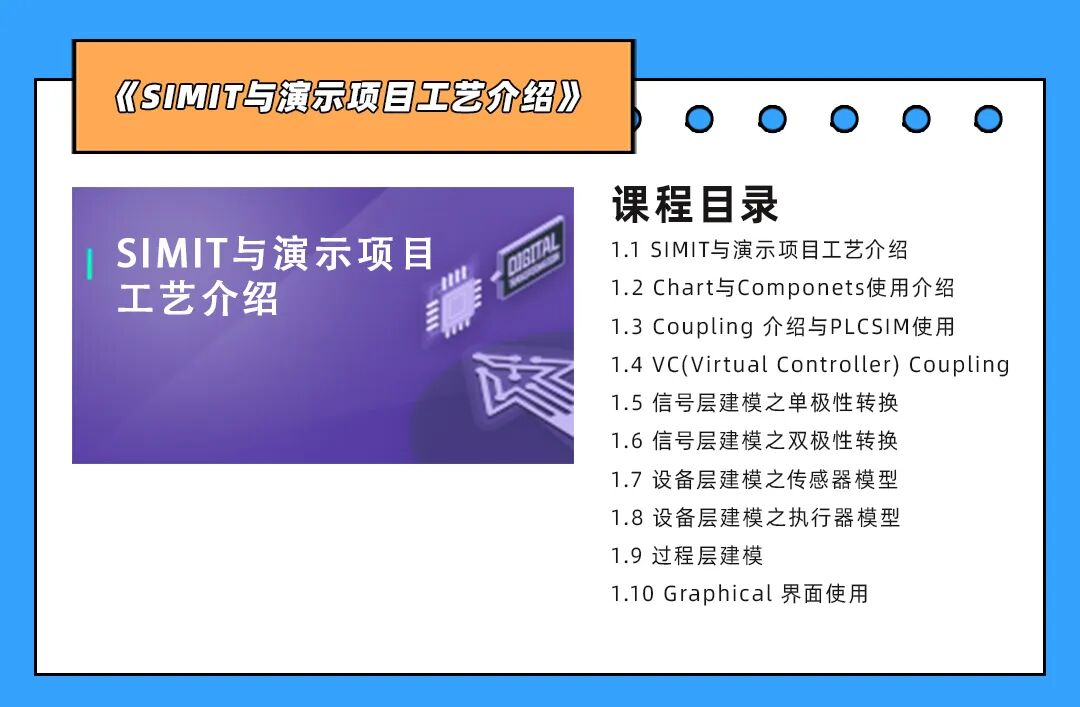
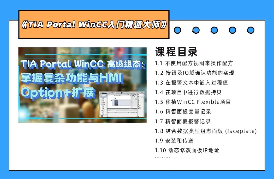
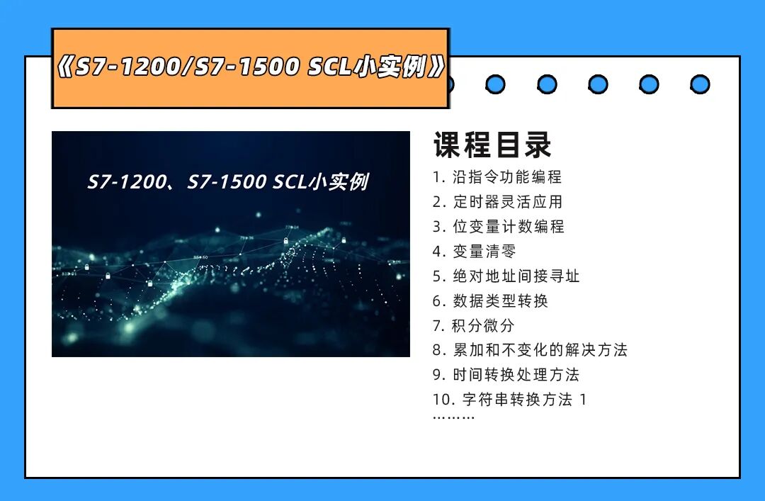
Swipe left to see more course catalogs
Prices start as low as 9.9 yuan (original price 139 yuan), feel free to scan the code to add customer service for course details:

More Benefits
Popular courses, official certification
 |
|
 |
 |
 |
 |