In modern industrial production, the application of PLCs (Programmable Logic Controllers) is becoming increasingly widespread. However, with the increase in usage frequency, operators have higher demands for PLCs. Today, we have compiled some practical tips for daily PLC applications to help you work more efficiently.
1. Grounding Issues: Ensure Stable System Operation
The grounding requirements for PLC systems are very strict. It is best to have a dedicated grounding system to avoid sharing grounding terminals with other devices, preventing current interference and logical errors. At the same time, analog signals can adopt a shielded floating ground technique, where the shielding layer of the signal cable is grounded at one point, and the signal loop is floating, with an insulation resistance to ground of no less than 50MΩ.
2. Anti-Interference Measures: Improve System Stability
The industrial environment is often harsh, with many high and low-frequency interferences. These interferences are generally introduced into the PLC through cables connected to field devices. Therefore, when designing and laying cables, some anti-interference measures should be taken. For example, analog signals should use double-shielded cables; high-speed pulse signals should use shielded cables; communication cables between PLCs should generally use cables provided by the manufacturer.
3. Eliminate Inter-Wire Capacitance to Avoid Malfunctions
There is capacitance between the conductors of the cable, and qualified cables can limit this capacitance to a certain range. However, when the cable length exceeds a certain limit, the capacitance value between wires may exceed the required value, potentially causing PLC malfunctions. To solve this problem, the following should be done: use twisted pair cables; minimize the length of the cables used; separate cables for interfering inputs; and use shielded cables.
4. Selection of Output Modules: Choose Appropriate Modules Based on Load Requirements
Output modules are divided into transistor, bidirectional thyristor, and relay types. The transistor type has the fastest switching speed but the smallest load capacity; the thyristor type has the advantage of being contactless and has AC load characteristics, but its load capacity is not large; relay outputs have both AC and DC load characteristics and a large load capacity. In conventional control, relay contact type outputs are generally selected first.
5. Handling Overvoltage and Overcurrent in Inverters: Protect Equipment Safety
When an inverter is running in deceleration, the motor enters a regenerative braking state, and the energy fed back to the inverter is stored in the filter capacitor, which may cause DC overvoltage protection to trip. The solution is to add a braking resistor externally to the inverter to dissipate the regenerative energy fed back from the motor to the DC side. Additionally, when an inverter drives multiple small motors, if one small motor experiences an overcurrent fault, it may cause other normal small motors to stop working. The solution is to install a 1:1 isolation transformer on the output side of the inverter.
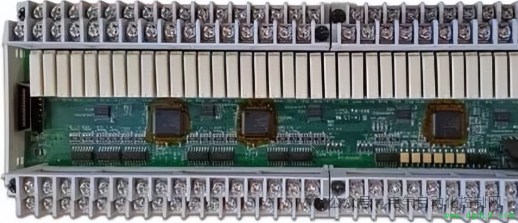
6. Mark Inputs and Outputs for Easy Maintenance: Improve Maintenance Efficiency
The PLC controls a complex system, and what can be seen are two staggered rows of input and output relay terminals, corresponding indicator lights, and PLC numbers. To facilitate maintenance, we can create a table and post it on the device’s control console or cabinet, indicating the number of each PLC input and output terminal along with the corresponding electrical symbols and Chinese names. This way, even electricians who are not familiar with the operation process or cannot read ladder diagrams can easily perform maintenance.
7. Infer Faults Through Program Logic: Quickly Locate Problems
Nowadays, various types of PLCs are commonly used in industry, and for low-end PLCs, the ladder diagram instructions are generally similar. A practical ladder diagram must have Chinese symbol annotations; otherwise, it is difficult to read. For electrical fault analysis, the reverse lookup method or reverse deduction method is generally used, which involves finding the corresponding output relay of the PLC from the fault point based on the input-output correspondence table and starting to trace back the logical relationships that satisfy its action. Experience shows that once one problem is found, the fault can generally be eliminated.
8. PLC Self-Fault Diagnosis: Focus on Peripheral Electrical Components
Generally speaking, PLCs are extremely reliable devices with a very low failure rate. Therefore, when searching for electrical fault points, the focus should be on the peripheral electrical components of the PLC, rather than always suspecting that there is a problem with the PLC hardware or program. This is crucial for quickly repairing faulty equipment and restoring production.
9. Fully and Reasonably Utilize Software and Hardware Resources: Reduce Costs and Improve Efficiency
Instructions that do not participate in the control loop or have already been executed before the loop should not be connected to the PLC; when multiple instructions control a task, they can be connected in parallel outside the PLC before being connected to an input point; try to utilize the internal functional soft components of the PLC, fully call intermediate states, making the program coherent and easy to develop. This also reduces hardware investment and lowers costs.
10. Other Considerations: Details Determine Success or Failure
Do not connect AC power lines to input terminals to avoid damaging the PLC; grounding terminals should be independently grounded and not connected in series with other devices, with a grounding wire cross-sectional area of no less than 2mm²; auxiliary power supplies have a small power output and can only drive low-power devices (such as photoelectric sensors); some PLCs have a limited number of occupied points (i.e., empty address terminals), do not connect wires to them; when there is no protection in the PLC output circuit, protective devices such as fuses should be used in the external circuit to prevent damage from load short circuits. Last but not least, the PLC emergency stop should use an external switch to ensure safety.
The above are some practical tips for daily PLC applications that we shared today. We hope this content can help you work more efficiently in practice!