Over 60,000 friends have followed the Industrial Control WeChat platform: Technical sharing, learning exchanges, industrial control videos
PLC program design is generally based on intuitive methods, meaning it relies on the learning experience of the circuit designer, which is relatively subjective and direct. It often involves a period of trial and error, debugging the program until it meets the required functions or actions; thus, the designed program varies from person to person. Apart from the original designer, users or maintenance personnel may find it difficult to understand the action flow, resulting in lower program readability. However, there are some patterns to follow in program design, although few books in the market mention this part. Here, with a spirit of sharing, we will discuss the process of converting a traditional electrical diagram into a ladder diagram using the example of a “Three-Phase Induction Motor Fault Alarm Control” circuit, hoping that this will help you in related circuit conversions or program designs.
1. Traditional Electrical Diagram
The known three-phase induction motor fault alarm control circuit’s traditional electrical diagram is shown in Figure 1.
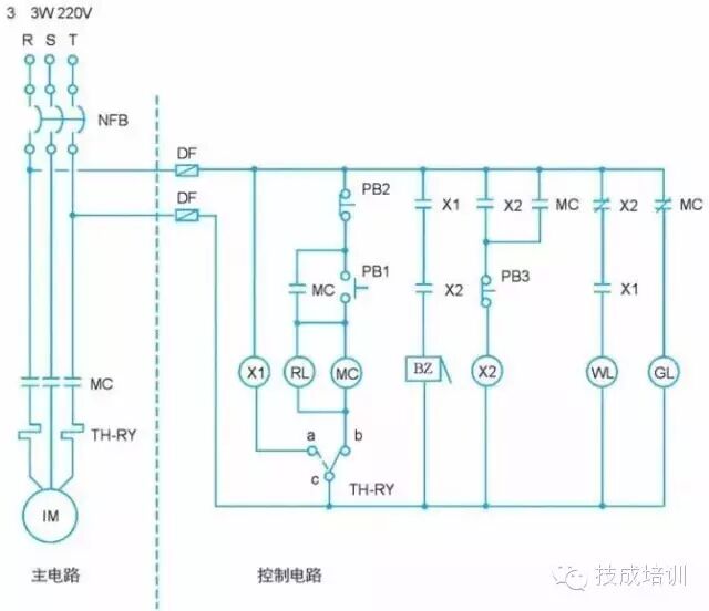 Figure 1: Three-Phase Induction Motor Fault Alarm Control Circuit Diagram
2. Action Description
1. When the power supply is normal, only the green light gl is on, and the motor does not operate.
2. Pressing the start button pb1 activates the electromagnetic contactor mc, causing the motor to run immediately, the indicator light rl turns on, and the green light gl turns off.
3. Pressing the stop button pb2 cuts off the power to the electromagnetic contactor mc, stopping the motor, turning off the indicator light rl, and turning on the green light gl.
4. If the motor is running and an overload or other fault causes the thermal relay th-ry to activate, the motor stops, the buzzer bz sounds an alarm, the indicator light rl turns off, and the green light gl turns on.
5. Pressing the button switch pb3 stops the buzzer bz alarm, turns on the white light wl, keeps the green light gl on, and turns off the red light rl.
6. After troubleshooting, pressing the reset lever of the thermal relay th-ry turns off the white light wl, keeps the green light gl on, and turns off the red light rl, allowing the motor to be restarted.
3. I/O Coding
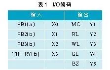
Using PLC means replacing hardware wiring with software programs. The main circuit in the traditional electrical diagram cannot be replaced by PLC; however, the control circuit can be. The first step in converting the traditional electrical diagram to a ladder diagram is I/O coding, which involves determining the corresponding external input/output terminal numbers in the PLC for the input/output components in the traditional electrical diagram, as well as the wiring method for external input components using a/b contacts, as shown in Table 1.
(a): External wiring using a contact method
(b): External wiring using b contact method
4. PLC External Wiring Diagram
After I/O coding the input/output components and deciding on the a/b contact wiring method for external input components, the PLC external wiring diagram is shown in Figure 2. The PLC model shown is the Fengwei Vigor-VB series, using NPN wiring, meaning the 24V terminal is connected to the S/S terminal.
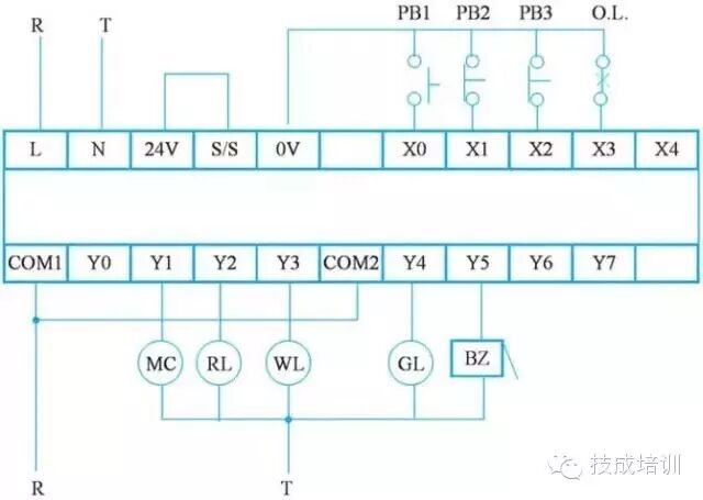 Figure 2: PLC External Wiring Diagram
5. PLC Ladder Diagram
The steps for program design in converting the traditional electrical diagram to a ladder diagram are as follows:
(1) Directly convert the control circuit in the electrical diagram to the corresponding ladder diagram. Since the PLC ladder diagram specifies that contacts must be at the front and output coils must be at the end of the circuit, the electrical diagram must be redrawn to adjust the positions of contacts and output coils to meet the requirements of the PLC ladder diagram. The redrawn electrical diagram is shown in Figure 3.
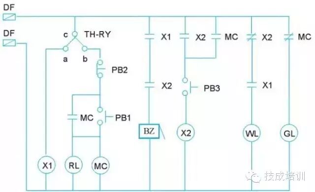 Figure 3: Redrawn Electrical Diagram
(2) Replace the input/output components in the electrical diagram with the component numbers from the I/O coding. It is important to note that the c-a and c-b contacts of th-ry should be separated and each become a control circuit, as shown in Figure 4.
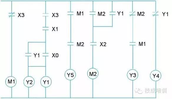 Figure 4: Electrical Diagram After I/O Coding
(3) Rotate the electrical diagram shown in Figure 4 by 90° to the left, then flip it upside down to obtain the PLC ladder diagram. However, due to:
(1) y1, x0 contacts,
(2) output coils y1 and y2 not conforming to the general programming software format, adjustments must be made, as shown on the right side of Figure 5.
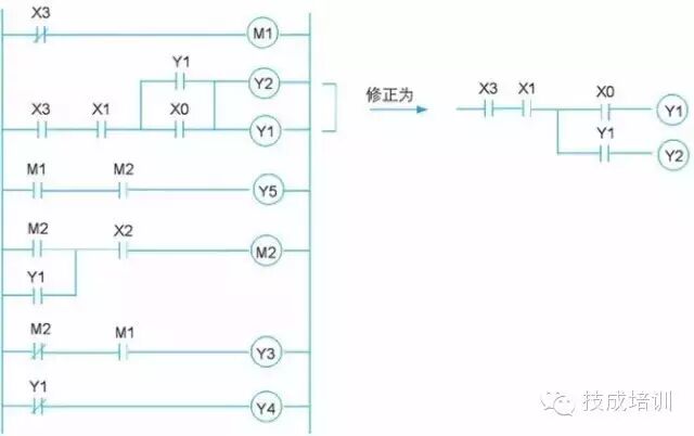 Figure 5: Adjusted and Corrected Ladder Diagram
※ If you use Visio to draw the electrical diagram, rotating it 90° to the left and then flipping it upside down becomes very easy.
(4) The ladder diagram drawn using programming software, as shown in Figure 6, is identical to the adjusted and corrected ladder diagram.
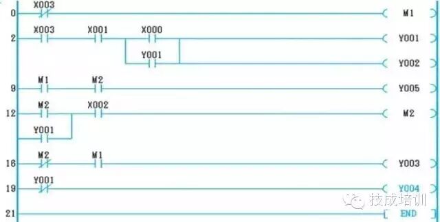 Figure 6: Ladder Diagram Drawn Using Programming Software
6. Instructions
The conversion of the ladder diagram to instructions is as follows:
7. PLC Wiring and Ladder Diagram Conversion
After the complete conversion of the traditional electrical diagram, the PLC external input/output wiring and ladder diagram are shown in Figure 7. After replacing hardware wiring with software programs, the PLC external input/output wiring and ladder diagram are as shown below.
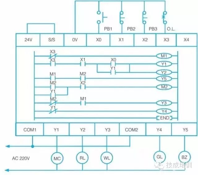 Figure 7: PLC After Replacing Hardware Wiring with Software Programs
8. Conclusion
The purpose of developing PLCs is to replace relay-based sequential control, meaning using software programs to replace hardware wiring. Therefore, by simply changing the software program, the control sequence can be altered to easily meet different control requirements. General PLCs are developed based on traditional relay control circuits, symbolizing the contacts and coils of relays. Once converted into a general ladder diagram or instructions, control can be achieved. However, the completed control circuit is based on the learning experience of the circuit designer, which is relatively subjective and direct, making it difficult for general users to understand the action flow, resulting in lower program readability.
Source: Internet

If this article has been helpful to you, please share it in your circle of friends to increase knowledge ❤
For more exciting content, please click on “Read the original text” below.