☝Click the blue text above to follow me.
I hope the suggestions at the end of the article will be helpful to you.
Hello everyone, this is Cat Dodo.“This is my 46th original article”
PLC (Programmable Logic Controller) is the “brain” of modern industrial automation, whether it is an automated production line, packaging equipment, or elevator and air conditioning control, PLC plays a key role.A good PLC program relies on a scientifically clear program framework.
Many PLC beginners, when they first start, only know how to “copy” ladder diagrams, resulting in messy programs that are difficult to debug. In fact, whether it is Siemens, Mitsubishi, or Omron, mastering a general PLC program framework is the foundational skill to becoming an engineer.
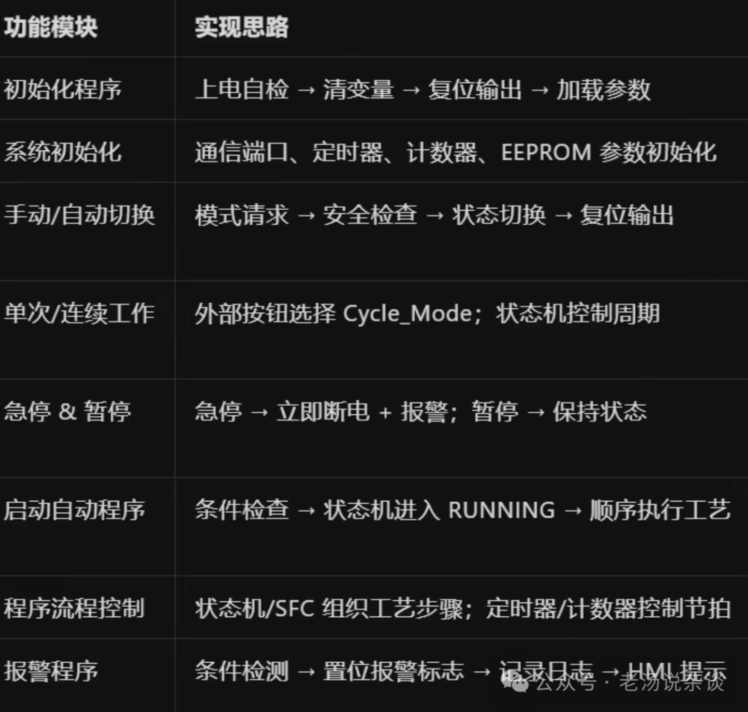
01. What is a PLC Program Framework?
In simple terms, a PLC program framework divides the entire control program into several functional modules and logical structures, making the program structure clear, easy to maintain, and convenient to expand.
Just like building a house requires a structural diagram, PLC programming also needs a “skeleton”. With a framework, subsequent function additions and fault troubleshooting become very convenient.
02. Common PLC Program Framework Structures
Generally speaking, PLC programs can be designed according to the following main parts:
1. Initialization/System Startup Section
- Power on, system reset, parameter initialization.
- Setting various initial states, clearing, alarm reset, etc.
2. Input Acquisition Section
- Collecting and filtering input signals from all sensors, buttons, switches, etc.
- Input debouncing and error detection can be set.
3. Manual/Automatic Mode Selection Section
- Determining the current operating mode (manual, automatic, debugging).
- Different modes have different program logic processing.
4. Main Control Logic (Sequential/Step/Function Section)
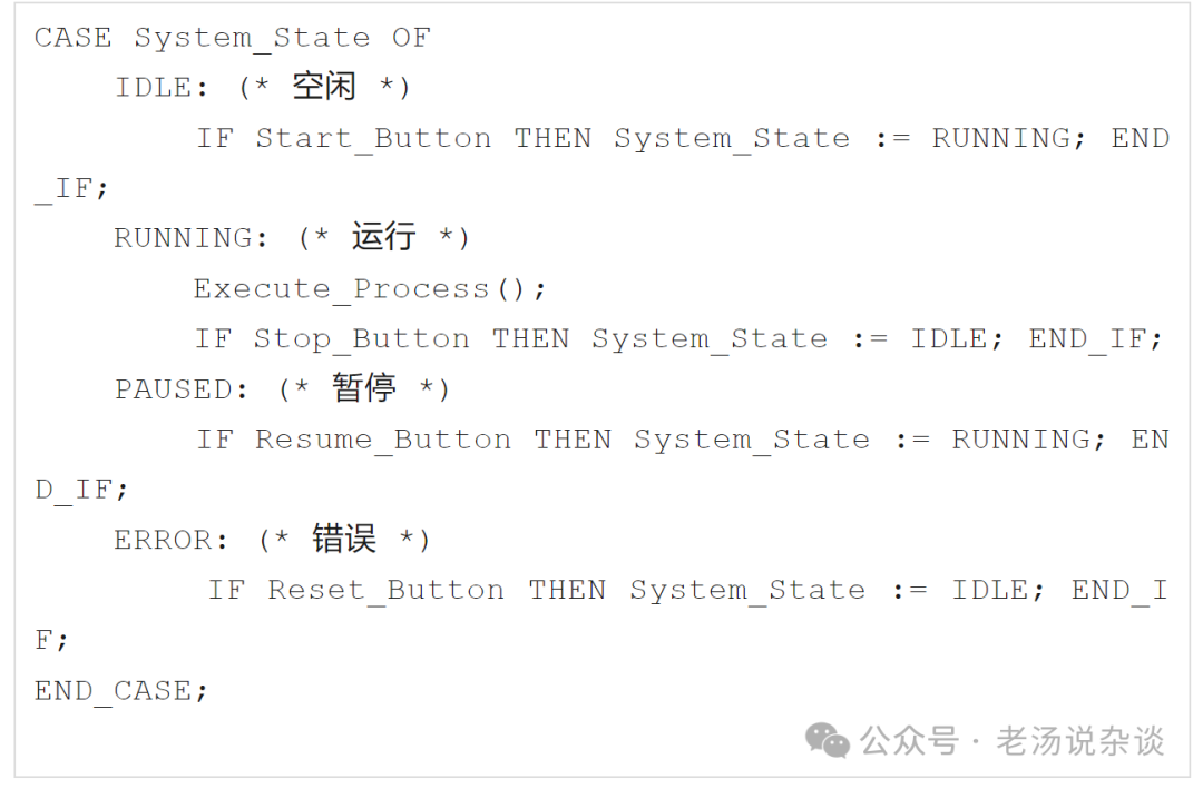
- Main process flow, equipment sequence control (such as step program, state machine).
- Action commands, process judgments, interlock protection.
5. Alarm and Protection Section
- Fault detection, alarm triggering, protective actions (such as over-temperature, over-pressure, emergency stop).
- Alarm signal collection, alarm output, alarm clearing.
6. Output Execution Section
- Driving various actuators (motors, valves, lights, buzzers, etc.) based on the main logic results.
- Output signal filtering, holding, interlocking.
7. HMI/Communication Interaction Section
- Data exchange with human-machine interface (touch screen), upper computer, remote monitoring.
- Status display, parameter setting, data upload.
8. Auxiliary Function Section
- Counting, timing, data recording, recipe management, etc.
03. Typical Code Structure of PLC Program Framework (Pseudocode Example)
Program Main Loop
├─ Initialization Section
├─ Input Signal Acquisition Section
├─ Mode Switching Judgment Section
│    ├─ Manual Control Logic
│    └─ Automatic Control Logic (Sequential/Step)
├─ Alarm and Protection Section
├─ Output Execution Section
├─ Communication and HMI Section
└─ Auxiliary Function Section
In actual PLC ladder diagram (LAD), function block (FB), structured text (ST) programming,
different organizational methods (such as OB blocks, subroutines, function blocks, etc.) can be used to implement the above framework.
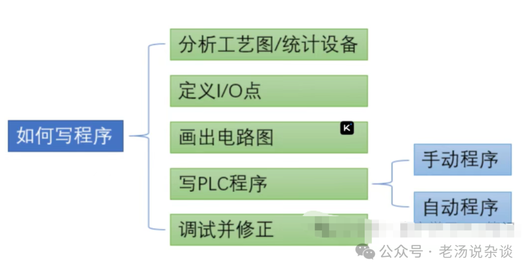
04. How to Build a High-Quality PLC Program Framework?
- Layered and Blocked: Each function is independent, making it easy to modify and expand.
- Clear Comments: Each section and step should clearly state its purpose for easier maintenance by others.
- Unified Variable Management: Classifying management of input, output, intermediate variables, alarm variables, etc.
- Comprehensive Exception Handling: Considering error protection for every action and every link.
- Testing Convenience: Leaving debugging interfaces for easy on-site simulation and troubleshooting.
05. Practical Application Examples of PLC Program Framework
Taking an automatic conveyor line as an example, the framework can be divided into:
- Power/Emergency Stop Detection and Initialization Section
- Sensor Signal Acquisition Section
- Automatic/Manual Mode Switching Section
- Conveyor Step Control Section
- Material Detection and Sorting Section
- Alarm and Shutdown Protection Section
- Indicator Light/Buzzer Output Section
- HMI/Upper Computer Communication Section
With this design, once new equipment needs to be added or functions expanded, you only need to add or delete in the corresponding module, without affecting the entire system.
06. Conclusion
The PLC program framework is the soul of industrial automation software engineering. A clear structure makes later maintenance easier and team collaboration more efficient.
Whether you are a PLC beginner or an experienced engineer, it is recommended to “first build the skeleton, then fill in the flesh”, so that your program will become more stable and easier to modify!
What structural chaos and debugging difficulties have you encountered in PLC programming? Feel free to leave a comment to share and grow together!
Light up the 【like and see】, let money and love flow to you.
For more insider information, please follow↓