This example is a solution for NEC infrared protocol decoding and LCD display based on the PIC16F877A, written using CCS C Compiler V5.015, and supports Proteus simulation (the compressed package includes the remote control model).
Detailed Explanation of NEC Infrared Protocol
1. Protocol Overview
The NEC protocol is a widely used infrared remote control protocol standard in consumer electronics (TVs, air conditioners, set-top boxes, etc.), characterized by the following features:
-
Carrier Frequency: 38kHz (duty cycle 1/3)
-
Modulation Method: Pulse Position Modulation (PPM)
-
Data Format: 32-bit frame structure (including address, command, and inverse code)
-
Transmission Distance: Typical 5-8 meters
-
Advantages: Simple hardware implementation, strong anti-interference capability
2. Protocol Frame Structure
A complete frame of data includes:
| Component | Bits | Description |
|---|---|---|
| Lead Code | – | 9ms high level + 4.5ms low level |
| User Code (Address) | 8 | Device identification (e.g., TV brand code) |
| User Code Inverse | 8 | User code bitwise inverse (for verification) |
| Command Code | 8 | Key function code (e.g., volume +) |
| Command Inverse | 8 | Command code bitwise inverse (for verification) |
Example Frame (Hexadecimal):
Address: 0x12 → Inverse: 0xED
Command: 0x34 → Inverse: 0xCB
Complete Frame: 0x12ED34CB
3. Encoding Logic
-
Logic 0: 560μs high level + 560μs low level (total period 1.125ms)
-
Logic 1: 560μs high level + 1.69ms low level (total period 2.25ms)
4. Special Signals
-
Repeat Code (sent when the button is pressed for a long time):
-
9ms high level + 2.25ms low level + 560μs high level
-
Does not carry data, indicates the previous command is repeated
-
Sent every 110ms
-
Lead Code Function:
-
Helps the receiver synchronize the clock
-
Distinguishes noise from valid signals
5. Transmission Timing
-
Starting Phase: Send lead code
-
Data Transmission: Send 32-bit data in LSB (least significant bit first) order
-
End Flag: Maintain high level for 560μs after the last bit of data
-
Repeat Code: If the button is held down, send the repeat code
6. Protocol Variants
-
Extended NEC: Uses 16-bit address (original address + extended address)
-
NECx2: Doubles the carrier frequency (76kHz) for high-speed transmission
-
Non-standard NEC: Some manufacturers modify timing parameters (decoding threshold needs adjustment)
7. Key Points for Hardware Implementation
-
Transmitter:
-
38kHz carrier emitted through infrared LED
-
Use timer to generate precise timing
-
Receiver:
-
Integrated receiver head such as VS1838B/HS0038
-
Outputs demodulated digital signal (no carrier)
Design Approach
-
Infrared Signal Acquisition: Use RB0 as an external interrupt pin to capture the falling edge signal of the NEC protocol
-
Protocol Decoding: Identify the lead code, logic 0/1, and repeat code through time measurement
-
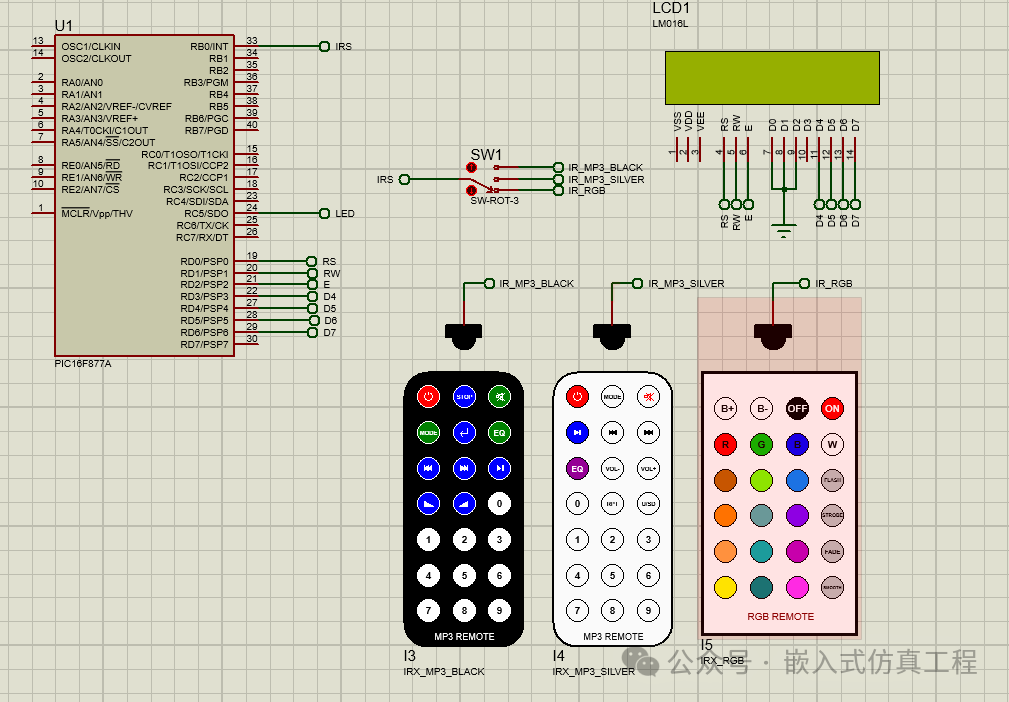
Multi-remote Switching: Single-pole triple-throw switch connects different remotes
-
LCD Display: 4-bit data mode drives LM016L, displaying the decoded key values
Main Program Code
void main(){
output_b(0); // PORTB initial state
set_tris_b(1);
lcd_init(); // Initialize LCD module
lcd_putc(‘\f’); // LCD clear
lcd_gotoxy(3, 1); // Go to column 3 row 1
lcd_putc(“NEC Decoding”);
delay_ms(2000);
lcd_putc(‘\f’);
lcd_gotoxy(1, 1); // Go to column 1 row 1
printf(lcd_putc, “Address:0x0000”);
lcd_gotoxy(1, 2); // Go to column 1 row 2
printf(lcd_putc, “Com:0x00 In:0x00”);
while(TRUE){
while(input(PIN_B0)); // Wait until RB0 pin falls
if(nec_remote_read()){
address = ir_code >> 16;
command = ir_code >> 8;
inv_command = ir_code;
lcd_gotoxy(11, 1);
printf(lcd_putc,”%4LX”,address);
lcd_gotoxy(7, 2);
printf(lcd_putc,”%2X”,command);
lcd_gotoxy(15, 2);
printf(lcd_putc,”%2X”,inv_command);
delay_ms(200);}
}
}
Key Configuration for Proteus Simulation
-
Microcontroller Settings:
-
PIC16F877A @ 4MHz
-
Configuration word: HS oscillator, disable watchdog
Infrared Receiving Circuit:
-
Three IR Receivers (VS1838B) outputs connected to a single-pole triple-throw switch
-
Common terminal of the single-pole triple-throw switch connected to RB0
LCD Connection:
PIC16F877A LM016L
RD0 ——> RS
RD1 ——> RW
RD2 ——> E
RD3 ——> D4
RD4 ——> D5
RD5 ——> D6
RD6 ——> D7
Function Description
-
Remote Control Switching:
-
Toggle the switch to select different remotes
-
LCD displays the current remote control number
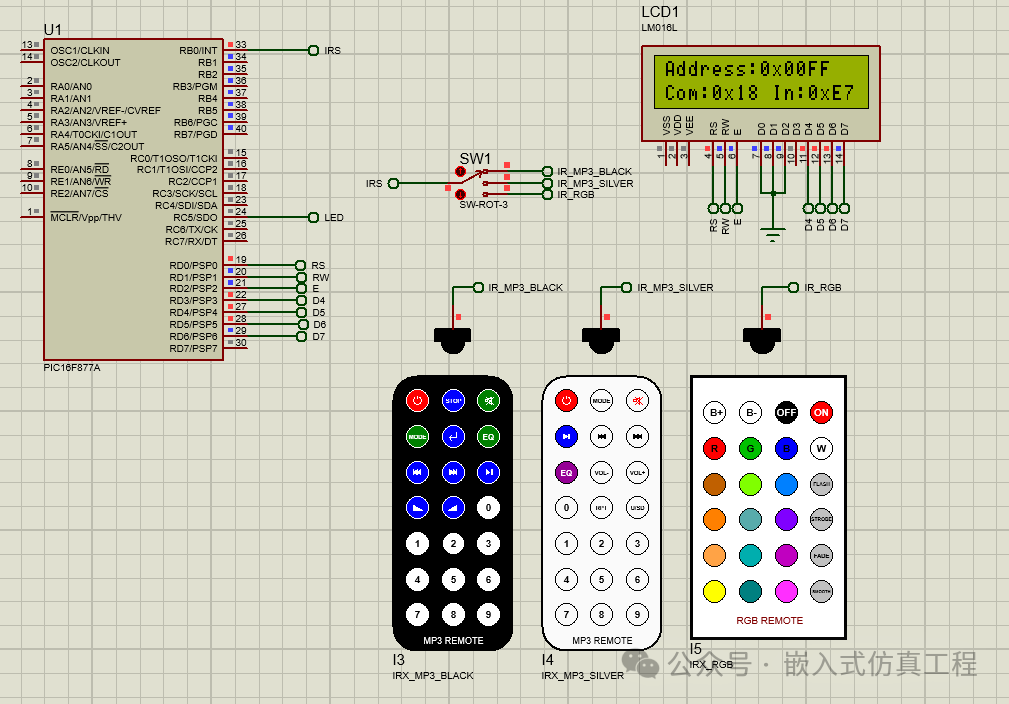
Decoding Display:
-
When decoded correctly, display “Address:0x00XX”, “Com:0xXX In:0xXX” (XX is the hexadecimal key value).
Protocol Handling:
-
Automatically identify NEC standard frames and repeat frames
-
Verify the inverse check of address and command
-
Timeout detection to prevent deadlock
Debugging Key Points
-
If decoding fails, check:
-
Power supply of the infrared receiver (needs 5V)
-
Interrupt trigger edge settings
-
Timing measurement threshold (can be adjusted ±10%)
If LCD display is abnormal:
-
Check control line connections
-
Adjust initialization delay
-
Confirm 4-bit data mode configuration
This solution fully implements multi-remote selection, NEC protocol decoding, and LCD display functions, and can be directly used for Proteus simulation and actual hardware deployment.
Welcome to follow (operation reference article: follow the public account and send message operation), click the blue text at the top “Embedded Simulation Project” or long press to identify the QR code to follow
Reply in the public account
1810
After receiving, automatically send the link to this project ofCCS C Compiler V5.015 project