Source WeChat Official Account: Jianwei Home (WeChat ID: jianweizhijia)
Table of Contents
Part One: Types and Usage Scenarios
1. Combined Power Supply
2. Embedded Power Supply
3. Wall-Mounted Power Supply
Part Two: Configuration Principles and Algorithms
1. Configuration Principles for New Installations
2. Configuration Principles for Shared Modifications
3. Capacity Algorithms
Part Three: Daily Management and Maintenance
1. Basic Components
2. Main Function Descriptions of Each Component
3. Daily Maintenance
Appendix 1: Lightning Protection Principles and Maintenance for DC Power Supply Systems
Appendix 2: Power Supply Selection Table
Abstract: This article focuses on the “types and usage scenarios, configuration principles and algorithms, daily management and maintenance” of power supplies.
Background: AC power can be rectified to obtain DC power. However, due to fluctuations in AC voltage and load current, the rectified DC voltage usually experiences a variation of 20% to 40%. To obtain stable DC voltage, a voltage regulation circuit must be employed. Depending on the implementation method, voltage regulators can be categorized into three types: linear voltage regulators, phase-controlled voltage regulators, and switching voltage regulators.
Compared to linear and phase-controlled voltage regulators, switching voltage regulators offer advantages such as high power conversion efficiency (65%~90%), less heat generation, compact size, lightweight, strong adaptability to wide voltage fluctuations in the power grid, and high stability of output voltage and load. Currently, almost all power supply systems in base station machine rooms utilize switching voltage regulators.
Part One Types and Usage Scenarios
Currently, there are three main types of switching power supplies used.
1. Combined Power Supply
(1) Configuration: Rack 48V/300A, 48V/600A; Rectifier module 50A (suggested N high +1 normal configuration).
(2) Usage Scenario: Used in indoor power supply scenarios with machine room conditions;
2. Embedded Power Supply
(1) Configuration: Rack 48V/200A, 48V/400A; Rectifier module 50A (suggested N high +1 normal configuration).
(2) Usage Scenario: Used in outdoor integrated cabinets;
3. Wall-Mounted Power Supply
(1) Configuration: Rack 48V/200A;
(2) Usage Scenario: Used for indoor distribution or in scenarios where there is no floor space to place cabinets.
Part Two Configuration Principles and Algorithms
Mainly includes “configuration for new installations, shared modifications, and capacity algorithms”.
1. Configuration Principles for New Installations
(1) The full capacity of the cabinet should consider long-term power demands, with a warning threshold of ≤80%. That is, (load current + charging current) / rated current ≤80%.
(2) The power supply system’s location should be as close as possible to the load center, with reasonable selection of line routing to minimize line losses.
(3) The number of rectifier modules should be based on the current load, and the current load should be determined based on actual load current (not considering battery charging current). The number should ideally follow an N+1 configuration; if N ≤ 8, reserve 1 unit; if N ≥ 9, reserve 2 units.
a.Precise Module Configuration: Only consider N+1 redundancy configuration based on load current (not considering charging current), prioritizing load power supply and extending battery charging duration;
b.High-Efficiency Module Adaptation: In practical work, N high-efficiency modules should be configured, with +1 normal module. During normal operation, high-efficiency modules operate, and the backup module is in sleep mode. When load current exceeds the capacity of N modules or when a high-efficiency module fails, the normal module is activated for emergency use;
c.Utilizing Sleep Technology: The switching power supply cabinet has module sleep functionality. Some modules can sleep to increase the load rate of the remaining modules. During normal power supply, high-efficiency modules operate while standard modules sleep; during battery equalization, standard modules activate, and during float charging, standard modules sleep.
(4) When selecting a system, consider advanced, safe, reliable, and energy-efficient products, or a mix of both.
(5) Three months is for current planning, one year for short-term planning, and two years for long-term planning.
2. Configuration Principles for Shared Modifications
(1) After adding new equipment, the configuration of the rectifier modules should only consider the load current requirements, with +1 redundancy, without considering battery charging current.
(2) If the number of DC output terminals is insufficient after adding new equipment, it should be met through innovative modifications or by adding a DC distribution box.
(3) Modifications to the switching power supply terminals: divided into primary and secondary terminals, utilizing innovative modifications or adding DC distribution boxes or new DCDUs to meet requirements:
Both primary/secondary terminals are sufficient: directly reuse.
Primary terminals are insufficient: add DCDU.
Both primary/secondary terminals are insufficient: add a DC distribution box.
3. Capacity Algorithms
Consider the actual power supply quality in the local area and the power supply assurance capability of the station comprehensively.
(1) Rack capacity algorithm:
A. Total load current = total device current + total battery equalization current. (Total device current = rated power of 60%/53V; total battery equalization current = 0.1C (C is the total battery capacity))
B. The capacity size is determined by combining configuration principles.
(2) Rectifier module algorithm
A. Number of modules N = total load current / 50 (rounded up)
B. Consider the difference between actual power and rated current comprehensively.
Part Three Daily Management and Maintenance
Mainly includes “basic components of the power supply, function descriptions of each component, and daily maintenance”.
1. Basic Composition (as shown in the figure)
The switching power supply system generally consists of “AC distribution, rectifier modules, monitoring modules, and DC distribution”, as shown in the overall structure below
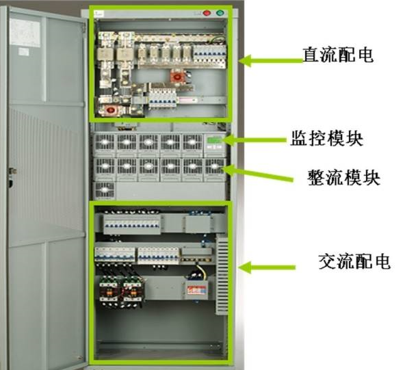 Note:The current direction flow of each part in the cabinet:
City power—Main circuit breaker—AC terminal and SPD–Rectifier branch circuit breaker—Rectifier—DC bus—DC SPD—Load fuse—Load..
2. Main Function Descriptions of Each Component
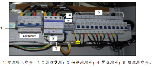
(1)AC Distribution Unit
A.Basic Composition(as shown in the figure)
B.Main Functions
AC distribution—— Inputs city power or generator power, distributing AC power to various AC loads. When city power is interrupted or abnormal (overvoltage, undervoltage, phase loss, etc.), the distribution panel can automatically issue an alarm signal. Some power systems can also automatically switch to a second city power source or cut off the AC power supply automatically to protect the system.
C.Main Component Devices
(A)AC input circuit breaker: AC access is generally through air circuit breakers, and the capacity of the AC access switch is the capacity of the AC distribution panel.
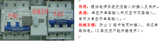
(B)Rectifier AC input switch: The AC distribution unit provides one AC input for each rectifier in the system, with switch capacity determined by rectifier capacity. (C)AC switching mechanism: Includes automatic and manual switching mechanisms. The automatic switching mechanism consists of contactors or ATS with mechanical-electronic dual interlocking. (D)AC sampling circuit: A circuit board consisting of transformers and rectifying devices that converts AC voltage, current, and frequency into electrical signals that the monitoring circuit can process. (E)AC switching control circuit: Completes automatic switching between two AC sources, over/under voltage protection, alarms, etc. (F)AC monitoring circuit: A microprocessor circuit specifically for processing various information from AC distribution in a distributed monitoring system, capable of completing signal detection, processing, alarming, displaying, and communicating with monitoring modules. (G)Type C and Type D lightning protection devices.
D.Detailed Description of Important Devices
(A)AC Input Circuit Breaker
(B)Type C Lightning Protection Device
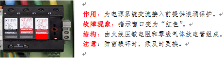
The commonly used lightning protection devices in DC switching power supplies are “varistors and gas discharge tubes“.
a. Varistor: When the voltage exceeds 385V, the resistance drops, and the higher the voltage, the lower the resistance;
b. Gas Discharge Tube: When the voltage exceeds 255V, the gas breaks down and conducts.
c. Lightning protection circuit breaker: When the varistor thermally breaks down, the live wire shorts to the neutral wire, causing the lightning protection circuit breaker to trip, preventing line fires. It must be closed during normal operation.
How to determine the quality of lightning protection devices: 1.Varistor: Green window – good; Red window – bad; 2. Gas discharge tube: Difficult to judge directly! Replace it together with the varistor; 3. DC lightning protection: All indicator lights on – good; Not all indicator lights on – bad.
Note: A detailed explanation of “Lightning Protection Principles and Maintenance for DC Power Supply Systems” is provided in the appendix.
(C)Rectifier Circuit Breaker
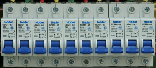 Function: The rectifier circuit breaker is used to control the input AC connection and disconnection of a single rectifier;
Note: One rectifier circuit breaker corresponds to one rectifier. When installing the rectifier, try to maintain a balanced load across the three-phase voltages, with the slot and phase line relationship being: 123456 corresponding to ABCABC.
(2)Rectifier Module
A.Basic Composition(as shown in the figure)
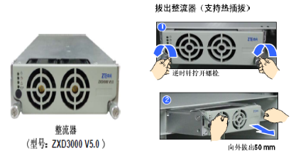
Function: Converts AC power (85V-295V) to DC power (42V-59V).
Features: Supports hot-swappable; fan automatic control.
Type: High efficiency (over 97%), normal efficiency (over 92%)
Capacity: 30A, 50A.
Phenomena: Green light 1 (AC input) always on – normal, Green light 2 (DC output) flashing – current limiting; Yellow light always on – alarm, Yellow light flashing – communication interrupted; Red light always on – fault; Green light 1 always on and Green light 2 off – sleep.
B.Main Functions
Rectifier Module—— Obtains AC energy from AC distribution, rectifies AC to DC, and outputs to the DC bus. Issues alarms or automatically protects when AC anomalies or DC output anomalies occur. If the rectifier module experiences severe faults, it automatically shuts down and exits operation.
C.Replacement Procedure (Hot-swappable)
1. Check the new rectifier module for any obvious transport damage.
2. Loosen the handle fixing screws of the rectifier module. Pull the module out of the rack. Be careful of burns.
3. Grasp the handle of the new rectifier module and slowly push the module into the cabinet, ensuring good connection of input and output sockets. 4. The module running indicator light will light up after a short delay, and the fan will operate.
5. Check if the new rectifier module operates normally. This includes: whether the monitoring module can recognize the new rectifier module; whether it shares current with other rectifier modules; when the rectifier module is pulled out again, observe if there are corresponding alarms on the monitoring module.
6. Secure the new module.
(3)DC Distribution Unit
Distributes DC energy from the DC bus to loads of different capacities and charges the battery. It should generate alarms or protections when DC power supply is abnormal, such as fuse breaking alarm, battery undervoltage alarm, battery over-discharge protection, etc.
A.Basic Composition(as shown in the figure)
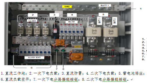
B.Main Functions
(A)Load power cut and battery protection
(B)Battery undervoltage alarm value: 45V (adjustable)
(C)Secondary load power cut (primary power cut) value: 44V
(D)Battery low voltage protection (secondary power cut) value: 43.2V
C.Technical Requirements
The DC distribution panel is located between the rectifier and communication loads, primarily for connecting the rectifier and battery pack and distributing DC loads. Its main technical requirements are as follows: (A) DC distribution panels of the same voltage and model should be able to be used in parallel. (B) Two battery packs can be connected. (C) Load distribution and capacity can be determined based on actual system needs. (D) In a low-resistance distribution system, when the DC panel carries rated load, the voltage drop in the discharge loop inside the panel should be ≤500mV. (E) It should have overvoltage, undervoltage, overcurrent protection, and low voltage alarm functions. (F) The battery charge and discharge loop and main output branches should be monitored.
D.Detailed Description of Important Devices
(1)Load Fuse and Circuit Breaker
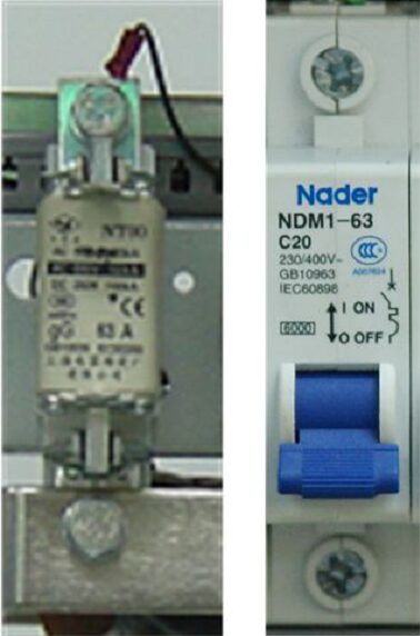
Function: Provides access and protection for load devices.
Principle: When the load device current exceeds the rated current of the fuse (circuit breaker), the fuse blows, and the circuit breaker trips, protecting the load device.
Note: 1. When the fuse blows, it must be replaced promptly; 2. When selecting, the fuse (circuit breaker) capacity should be 1.5-2 times the load current.
(2)Shunt Resistor
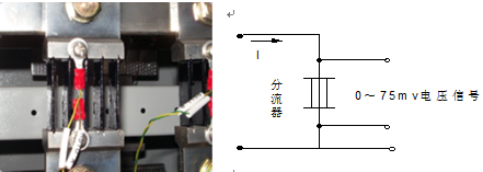
Function: A precision resistor used to measure load and battery currents (“one shunt for each load, battery group 1, and battery group 2” is used to detect actual current size).
Principle: Converts current signals into millivolt-level voltage signals. The shunt sends a 0-75mV voltage signal to the monitoring unit, which calculates the actual current based on the set specifications of the shunt.
At the same time, the directional function of the shunt can display the charging current (positive) when the battery is charging and the discharging current (negative) when discharging.
Specification: 300A/75mV;
(3)DC Contactor
Function: Battery protection, load power cut (including primary power cut, battery power cut).
Principle: The contactor uses a normally closed connection. When receiving a power cut signal (45V, 43V), the coil is energized, and the contactor disconnects; when city power is restored, the contactor automatically closes.
Disconnection Phenomenon: The bus voltage is normal (53.5V), while the primary power cut or battery power cut voltage is 0.
Note: In practical work, due to faults in other devices, the DC contactor may disconnect. In this case, it is necessary to disconnect the faulty device and forcibly restore power.
Starting with ZJ, normally closed type, normally conducting. There is no potential difference at both ends.
Usage Instructions: Coil rated voltage 48V; normally closed type (closed without power, opened with power).
(4)Monitoring Unit
The monitoring module is an intelligent device in the high-frequency switching power supply system that uniformly manages the operation of the switching power supply system. This module monitors, controls, and manages the operational status of the switching rectifier modules, AC and DC distribution panels, and batteries in real-time, according to predetermined working procedures through internal communication interfaces. A switching power supply system has one monitoring module, which can simultaneously monitor multiple high-frequency switching rectifier modules and distribution devices. Additionally, through RS232/485 external interfaces, it can be integrated into the upper-level monitoring management system, sending and receiving corresponding information, executing commands from the monitoring system; it also has the function of storing various parameters and operational information, allowing maintenance personnel to adjust operational parameters on-site and display the operational state and parameters of the system in real-time.
A.Basic Composition(as shown in the figure)
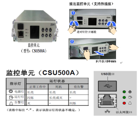
Function: Completes system operational status, battery management, various parameter settings, viewing real-time and historical alarms, and data remote transmission functions.
Phenomena: Green light 1 (DC power supply) always on – normal, Green light 2 (operational status) flashing – normal; Red light flashing – alarm.
Note: If the monitoring unit is damaged, it should be replaced promptly.
Examples of system operation issues caused by monitoring unit damage: 1. When the battery discharges, the monitoring unit cannot execute power cut protection (DC contactor failure), which may lead to deep battery discharge; 2. The rectifier can only output 53.5V DC to charge the battery pack (default is float charge); 3. The battery charging current is unrestricted (the battery charging management function fails); 4. Dynamic environment monitoring is interrupted (fails).
B.Main Functions:1. Display Function: The monitoring module can display various operational information of the system on its LCD screen, such as AC input voltage, DC output voltage/current, battery equalization/float charge status, etc. 2. Parameter Setting: Users can input and modify the operating parameters of the power supply system via the keyboard and display screen. These parameters will affect the operation of the entire system in subsequent operation, so it is essential to ensure that the input parameters match the actual situation; otherwise, the monitoring module cannot monitor the power supply system correctly. 3. Control Function: The monitoring module issues corresponding action commands to the monitored objects based on the system’s operational status, mainly including: (1) Changing the current limiting point of the rectifier module; (2) Controlling the on/off state and equalization/float charge state of the rectifier module; (3) Battery undervoltage protection, etc. 4. Alarm Function: The monitoring module can monitor the switch quantities, analog quantities, and battery operational status of the system based on collected data, and further process relevant information for alarms. 5. Historical Records: The monitoring module stores some important states and data from the power supply system’s operation process based on time or other conditions for future inquiries. The monitoring module can provide five historical alarm messages, each including alarm type, start time, and end time, ensuring they do not disappear after power loss. Users can browse at any time on the LCD screen. 6. Battery Management Function: The monitoring module can adjust the battery charging method, charging current, and implement various protective measures (such as charging current limiting, float charge temperature compensation, secondary power cut, and battery protection) based on user-defined data (such as charging current limiting value, equalization/float charge conversion current value, secondary power cut voltage value, and battery protection voltage value, etc.).
3. Daily Maintenance Section
(1) Electrical Connection Testing
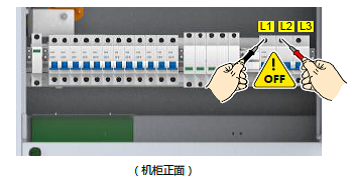
A.Testing for Short Circuit Faults in the AC Input Circuit
Operation Steps:
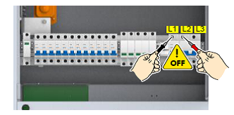
1. Set the external power switch of this device (in the AC distribution box) to OFF.
2. Set the AC input circuit breaker in this device to OFF.
3. Set the multimeter to the buzzer mode.
4. Test for short circuit faults at the AC input circuit breaker of this device.
The testing contact inspection standards are as follows:
|
AC Input Mode |
Testing Contact |
Inspection Standards |
|
Three-Phase AC Input |
L1-L2, L2-L3, L3-L1 |
1. Buzzer does not sound, indicating no short circuit fault, inspection result is qualified; 2. Buzzer sounds, indicating a short circuit fault exists, need to find the fault point and reconnect the cables. |
|
L1-N, L2-N, L3-N, |
||
|
L1-PE, L2-PE, L3-PE, |
Example: Testing for short circuit faults between AC input terminals L1 and L2
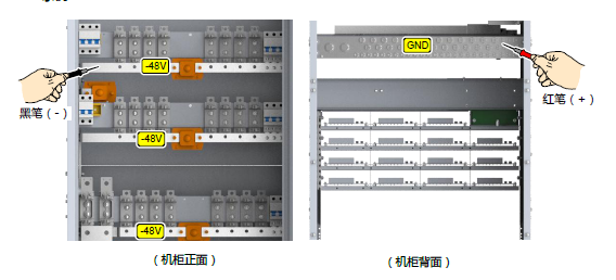
B.Testing for Short Circuit Faults in the DC Output Circuit
Operation Steps: 1. Set the multimeter to the buzzer mode;
2. Test for short circuit faults in the DC output circuit.
The testing contact inspection standards are as follows:
|
Testing Point |
Inspection Standards |
|
Black Probe -48V Bus |
1. Buzzer does not sound, indicating no short circuit fault, inspection result is qualified; 2. Buzzer sounds, indicating a short circuit fault exists, need to find the fault point and reconnect the cables. |
|
Red Probe GND Bus |
Example:
C.Testing AC Input Voltage
Operation steps are as follows:
1. Ensure that the AC input circuit breaker in this device is still set to OFF.
2. Set the external power switch (in the AC distribution box) to ON.
3. Set the multimeter to the AC voltage mode.
4. Test the AC input voltage at the position of the AC input circuit breaker in this device.
5. After completing the test, set the external power switch of this device to OFF.
The testing contact inspection standards are as follows:
|
AC Input Mode |
Testing Contact |
Inspection Standards |
|
Three-Phase AC Input |
N-PE |
1. Zero-ground voltage should be less than 5V. If the requirement is not met, the user must modify the power grid to reduce the zero-ground voltage difference; 2. Phase voltage should be in the range of 80V ~ 300V. If the requirement is not met, it is recommended to activate generator power. |
|
L1-N, L2-N, L3-N, |
Example: Testing the voltage between AC inputs L1 and L2
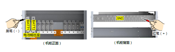
D.Testing the Terminal Voltage of the Battery Pack
Operation Steps: 1. Set the multimeter to the DC voltage mode.
2. Test the terminal voltage of each battery pack at the fuse holder position, and record the test values in the table below.
Testing Points and Inspection Standards
|
Testing Object |
Testing Contact |
Terminal Voltage |
Inspection Standards |
|
Battery Pack-1# |
Red Probe: GND Bus |
1. Testing value is positive, indicating qualified inspection; 2. Testing value is negative, indicating that the battery cable polarity is reversed, indicating unqualified inspection. |
|
|
Black Probe: Output Side of Battery Circuit Breaker 1 |
|||
|
Battery Pack-12# |
Red Probe: GND Bus |
||
|
Black Probe: Output Side of Battery Circuit Breaker 1 |
Example: Testing the terminal voltage of battery pack 1
(2) Suggestions for Power Supply Settings1. Power supply settings must match the actual conditions of the base station site and must not use factory default values; 2. Focus on battery management and correct number of power supply modules in the power supply settings (some manufacturers do not require module quantity settings in adaptive systems); 3. The primary and secondary power cut settings for switching power supplies: should be set based on the type of base station, long distances, battery capacity, and load conditions. For 2.5G transmission stations and transmission links with many upper and lower stations, to ensure transmission power supply, it is advisable to set the primary power cut value to 46V and the secondary power cut value to 43.2 (44)V; 4. For ordinary base stations, the primary power cut value is recommended to be set to 45.6V, and the secondary power cut value to 44.4V; 5. For terminal stations (which do not require protection for transmission), both primary and secondary power cuts should be set to 44V; 6. DC low voltage alarm value: for transmission node stations, important stations, and high mountain stations, the low voltage alarm value should be set to 48V, while ordinary base stations should be set to 47V; 7. For ordinary stations: charging current limiting value: 0.1C10, scheduled equalization time of 3-6 months, for stations with frequent power outages, increase the equalization limiting value to 0.15-0.2C10 to speed up battery charging; scheduled equalization time of 1-2 months.
Appendix 1: Lightning Protection Principles and Maintenance for DC Power Supply Systems
According to the specifications for high-frequency switching rectifiers for communication, DC switching power supplies are equipped with Type C lightning protection devices. Experienced power supply engineers understand the wiring methods for lightning protection devices and are familiar with the causes and handling methods of lightning protection alarms, but may not be clear about the details. The industry believes that Emerson power supplies pay attention to lightning protection design and do a good job with system lightning protection, but lightning protection issues are system engineering, not just having a power supply equipped with lightning protection devices that can completely solve the problem. If one can fully understand the lightning protection philosophy of the power supply system, it will not only help analyze equipment failures but also assist in building a highly reliable communication power system, providing strong support for the communication network.
1. The Principle of Overcurrent from Lightning Strikes
The invasion of lightning current first manifests as overvoltage, which occurs when there is a discharge path, generating lightning current. Whether due to direct lightning strikes causing line waves or electromagnetic induction overvoltage, it is the same. There are two types of overvoltage: common-mode overvoltage and differential-mode overvoltage, as shown in Figure 1.
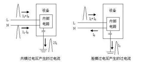
Figure 1 Common-mode and Differential-mode Overvoltage, Overcurrent
Due to the widespread existence of parasitic capacitance, lightning overvoltage can break down air or insulators at normal pressure, forming powerful lightning currents that can damage equipment.
To suppress the effects of lightning, energy should be discharged to the ground before it enters the equipment. For common-mode overvoltage, lightning protection devices (also known as surge protection devices) should be installed between the input cable and the lightning protection ground; for differential-mode overvoltage, lightning protection devices should be installed between the live wire and neutral wire of the input cable. Since lightning current is a surge current, lightning protection devices are a type of surge suppression protective device (Surge Protection Device), abbreviated as SPD.
2. Characteristics of Commonly Used Lightning Protection Devices
Commonly used lightning protection devices in DC switching power supplies are varistors and gas discharge tubes.
1. Varistor
Varistors are voltage-limiting devices. When a working voltage is applied across its terminals, the resistance is very high, and the leakage current is in the microampere range. As the terminal voltage increases, the resistance of the varistor decreases, and when the terminal voltage exceeds a certain value, the resistance drops sharply, allowing leakage currents of up to 20~40KA, forming a lightning discharge path. When the voltage drops back to the working voltage, the leakage current of the varistor rapidly decreases, restoring its original state.
The main parameters of the varistor commonly used in DC switching power supplies are as follows, with key parameter meanings shown in Figure 2.
Uc: Maximum continuous operating AC voltage, generally 385V.
U1mA: Nominal voltage, the voltage applied when the leakage current reaches 1mA, generally 630V.
UP: Residual voltage, the maximum voltage across the varistor after voltage limiting, generally 1500V.
In: Rated current-carrying capacity, able to safely discharge multiple lightning currents within the rated current-carrying capacity, generally 20KA.
Imax: Maximum current-carrying capacity, able to safely discharge once, generally 40KA, after which the varistor may be damaged.
Additionally, the response time of the varistor is also critical, generally between 10~100ns.
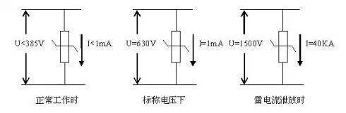 Figure 2 Characteristics of Common Varistors
As the working time increases, especially after multiple lightning current discharges, the leakage current of the varistor gradually increases. If the voltage applied is 90% of the nominal voltage U1mA, the leakage current reaches 1mA, indicating that the performance of the varistor is no longer acceptable, and it needs to be replaced. Based on this, detecting the performance of the varistor can be relatively easy.
There are many industry standards and international standards related to lightning protection devices, which have not yet been unified. Generally, it is required that varistors can withstand five positive and negative impacts of In current, one positive and negative impact of Imax current, and 100 impacts of 10% In current. When varistors fail, they exhibit short-circuit behavior, and the window changes from green to red; occasionally, varistors may explode and break, exhibiting open-circuit behavior.
2. Gas Discharge Tube
Gas discharge tubes are switch-type devices mainly composed of electrodes and the gas gap between them. When the voltage applied across the gas discharge tube is below the trigger voltage, it remains in an open circuit state with virtually no leakage current. When the voltage exceeds the trigger voltage, the gap breaks down, and it can be considered short-circuited. The trigger voltage depends on the type of gas discharge tube and has a certain light-sensitive effect, meaning that the deviation can be significant under light and dark conditions. The commonly used gas discharge tube in DC switching power supplies has a long-term withstand working voltage of 255V and a trigger voltage of around 400V. When the voltage across it drops back to the working voltage, the gap cannot extinguish the arc, which is the continuation current issue of the gas discharge tube. The extinguishing voltage of the gas discharge tube is very low, generally between 20-50V, so it should not be installed between the live wire and neutral wire or between the live wire and ground wire. Figure 3 illustrates the general characteristics of gas discharge tubes.
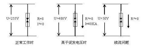 Figure 3 Characteristics of Common Gas Discharge Tubes
Gas discharge tubes have similar key parameters to varistors, such as UC, UP, In, Imax, etc. When gas discharge tubes fail, they exhibit open-circuit behavior, and occasionally they may short-circuit due to deformation of the gas discharge tube.
3. Kelvin Wiring Method
Since lightning currents are very large, the inductance of any long cable cannot be ignored. If the cables on either side of the lightning protection device are long, the voltage applied to the equipment equals the residual voltage of the lightning protection device plus the induced voltage on the cable, as shown in the left diagram of Figure 4, which is dangerous for the equipment. To reduce the residual lightning overvoltage applied to the equipment, the wiring method shown in the right diagram of Figure 4 should be used, which is called the Kelvin connection method.
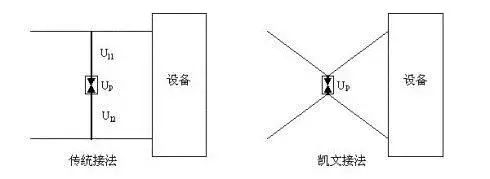 Figure 4 Conventional Connection Method and Kelvin Connection Method
When implementing the Kelvin connection method, it may not be possible to connect both incoming and outgoing cables directly to the lightning protection device, but the distance between the crossing point of the incoming and outgoing cables and the connection terminal of the lightning protection device should be minimized, generally not exceeding 0.5 meters.
4P Lightning Protection Device
A 4P lightning protection device refers to a lightning protection device composed of four varistors, as shown in Figure 4. There are only a few 4P lightning protection devices in the Chinese market, but in other countries like India, the lightning protection devices configured for DC switching power supplies are mostly 4P.
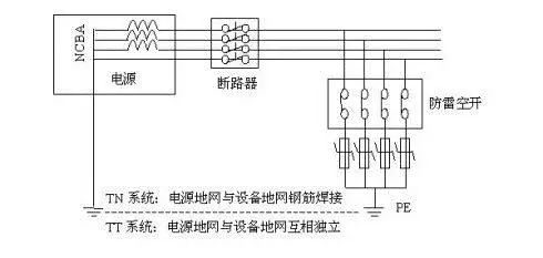 Figure 5 Wiring Method for 4P Lightning Protection Device
When a varistor in a certain phase fails short, the phase current returns to the power supply through the ground. Since the TN power supply system has a direct metallic connection between the power supply grounding network and the equipment grounding network, the resistance is very low, and the short-circuit current is very large, causing the lightning protection circuit breaker to trip, quickly disconnecting the lightning protection device from the power supply. However, if a 4P lightning protection device is used in a TT power supply system (such as base station power supply), since the power supply grounding network and the equipment grounding network are not directly connected, the short-circuit current flows back to the power supply through the relatively high-resistance ground. According to the communication power supply and air conditioning maintenance regulations, the grounding resistance of the base station should be less than 5Ω, and the total loop resistance may reach 10Ω, resulting in a short-circuit current of only 22A. The lightning protection circuit breaker may not trip, and sustained strong current may cause the wiring and lightning protection device to catch fire.
5. 3P+1 Lightning Protection Device
In China, the power supply systems of large communication stations generally use TN methods, allowing for the use of 4P lightning protection devices. Many medium and small stations tend to use TT power supply systems and should opt for 3P+1 lightning protection devices, which consist of three varistors and one gas discharge tube, as shown in Figure 6.
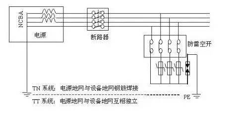 Figure 6 Wiring Method for 3P+1 Lightning Protection Device
The first difference between 3P+1 and 4P lightning protection devices is that the varistors are installed between the phase line and the neutral line, effectively discharging differential-mode lightning overvoltage, while the common-mode overvoltage is discharged by the gas discharge tube. Since the response time of the gas discharge tube is longer than that of the varistor, the common-mode overvoltage on the phase line cannot be discharged before the gas discharge tube responds, and the total response time of the lightning protection device is the sum of the response times of the varistor and gas discharge tube. Therefore, it is necessary to prioritize the use of gas discharge tubes with faster response speeds.
The second difference between 3P+1 and 4P lightning protection devices is that the gas discharge tube is used as the lightning protection device between the neutral line and ground line. The gas discharge tube has continuation current issues, and its low extinguishing voltage can further reduce the residual voltage on the neutral line, which is beneficial for the normal operation of the load.
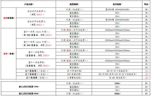
Appendix 2: Power Supply Selection Table
Network Optimization Mercenary Submission Email: [email protected]
Long press the QR code to follow