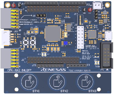
Recently, RT-Thread engineers completed the BSP adaptation based on the Renesas CPK-RA2L1 development board, supporting drivers for peripherals such as GPIO, UART, I2C, SPI, ADC, DAC, PWM, CAN, on-chip Flash, Watchdog, RTC, etc. With the support of Renesas engineers, the power component (low power LPM) adaptation was completed. Actual measurements show that the chip can achieve a minimum average current of about 0.696uA in the Software Standby phase. This note records the adaptation and application of low power.
You can view the RA MCU BSP at the following link:
https://github.com/RT-Thread/rt-thread/tree/master/bsp/renesas
Tutorial for creating BSP for Renesas RA series MCU development boards:
https://www.rt-thread.org/document/site/#/rt-thread-version/rt-thread-standard/tutorial/make-bsp/renesas-ra/RA%E7%B3%BB%E5%88%97BSP%E5%88%B6%E4%BD%9C%E6%95%99%E7%A8%8B
Before introducing low power, let’s understand the key features of the RA2L1 MCU product family
-
48MHz Arm Cortex-M23 CPU core
-
Supports a wide operating voltage range of 1.6V-5.5V
-
Ultra-low power consumption, providing 64μA/MHz operating current and 250nA software standby current, with a quick wake-up time of less than 5µs
-
Utilizes Renesas’ 110nm low-power process for operation and sleep/standby modes, and is specifically designed for battery-driven applications with a special power-off mode
-
Flexible power supply modes allow for lower average power consumption to meet various application needs
-
Integrates a next-generation innovative capacitive touch sensing unit, eliminating the need for external components and reducing BOM costs
-
Reduces system costs through high-precision (1.0%) high-speed oscillators, temperature sensors, and various power supply interface ports
-
Background running data flash, supporting one million erase/program cycles
-
Available in LQFP package, covering 48-pin to 100-pin packages
Basics of Low Power
The essence of low power is that the CPU stops working when the system is idle, and continues to work after being awakened by interrupts or events. In RTOS, there is usually an IDLE task, which has the lowest priority and remains in a ready state. When high-priority tasks are not ready, the OS executes the IDLE task. Generally, without low power processing, the CPU loops executing no-op instructions in the IDLE task. RT-Thread’s power management component effectively reduces system power consumption by managing the CPU, clocks, and devices in the IDLE task.
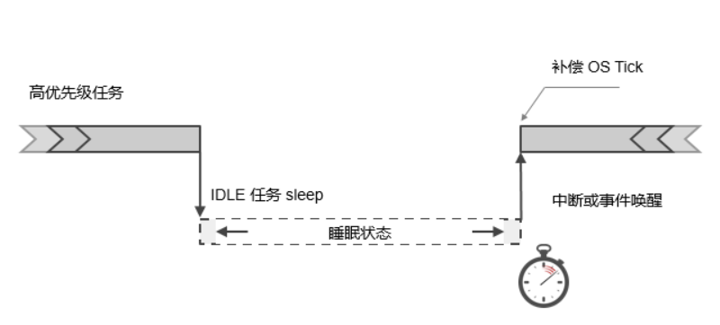
As shown in the figure above, when a high-priority task ends or is suspended, the system enters the IDLE task. After executing the IDLE task, it will determine whether the system can enter sleep mode (to save power). If sleep is possible, some hardware modules will be turned off based on the chip situation, and the OS Tick is also likely to enter a paused state. At this time, the power management framework will calculate the next timeout based on the system timer and set a low power timer, allowing the device to wake up at this point and perform subsequent work. When the system is awakened (by a low power timer interrupt or other wake-up interrupt sources), it also needs to know how long it has been asleep and compensate the OS Tick, adjusting the OS tick value to a correct value.
PM Component
The PM component is a basic functional component designed for power management in the RT-Thread system. The component adopts a layered design concept, separating architecture and chip-related parts, and extracting common parts as the core. It supports management switching between various operating modes and sleep modes, as well as management of low power timers.
The PM component has the following features:
-
PM component manages power consumption based on modes
-
PM component can automatically update device frequency configurations according to modes, ensuring normal operation in different operating modes
-
PM component can automatically manage device suspension and recovery according to modes, ensuring correct suspension and recovery in different sleep modes
-
PM component supports optional sleep time compensation, allowing OS Tick-dependent applications to use it transparently
-
PM component provides device interfaces to upper layers; if the device file system component is used, file system interfaces can also be used for access
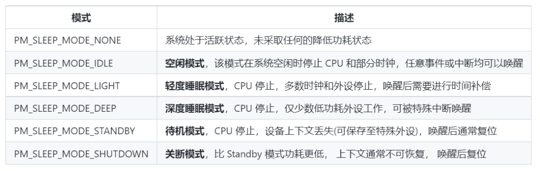
The sleep modes supported by the PM component are:
LPM Features of RA Series
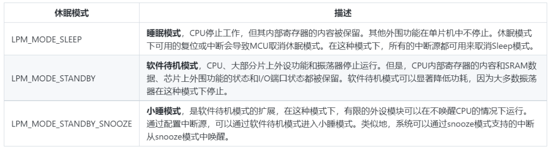
The types of LPM supported by the RA2 MCU are:
-
Sleep mode
-
Software Standby mode
-
Snooze mode
Low power mode transitions and trigger sources are shown in the figure:
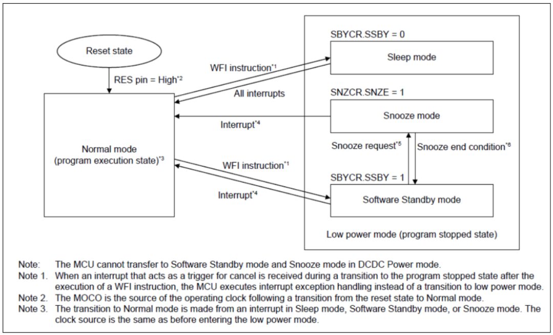
The switching between different modes is shown in the figure, which also shows the power consumption relationship of the three modes: Sleep > Snooze > Standby.
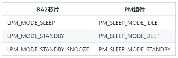
The sleep modes of the RA2 chip correspond to the mode relationships of the PM component:
Configuring LPM Features
To use the LPM features of the RA2 series chips, navigate to the bsp\renesas\ra2l1-cpk directory.
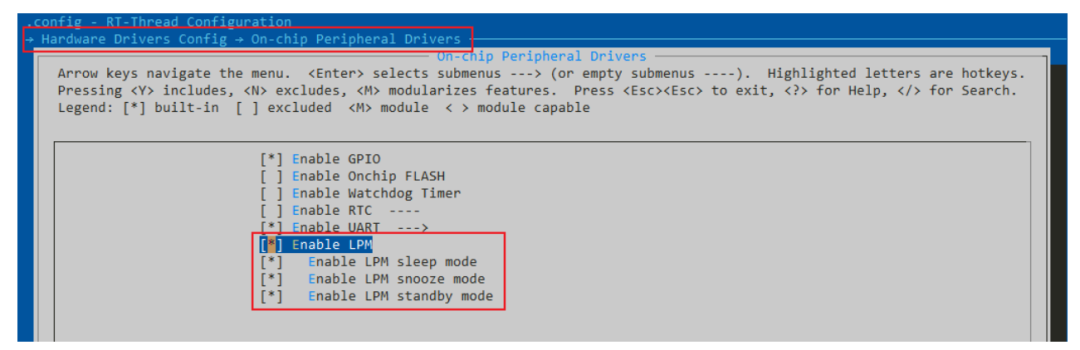
-
In menuconfig, enable the LPM driver, check the sleep modes to be activated, then save the configuration and generate the MDK5 project.
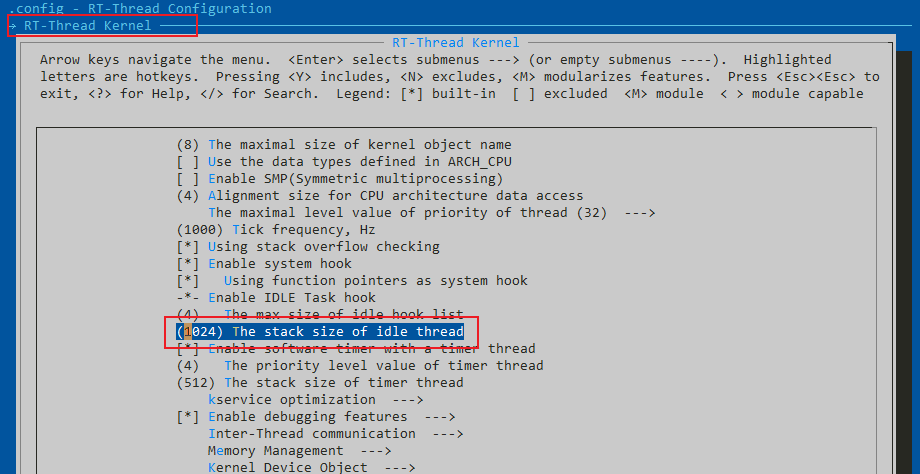
-
After opening the PM component and driver, increase the stack size of the idle thread to 1024.
-
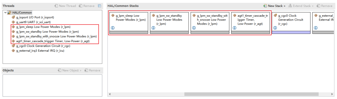
Open the generated MDK5 project project.uvprojx, then open the FSP configuration tool to add LPM-related configurations. The following image shows the stack to be added, including configurations for the three LPM modes and the low power timer AGT1.
-
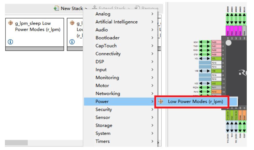
Create LPM as shown in the figure, configuration needs to be done according to the mode used, and different modes require creating different r_lpm. Below, we will separately introduce the configuration of the three different modes, and the creation steps will not be repeated.
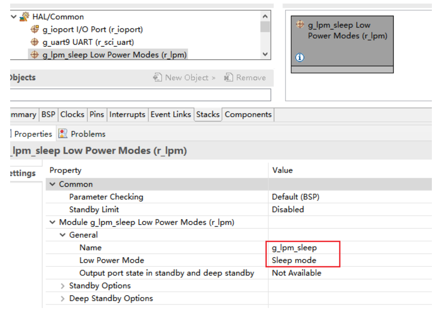
Sleep Mode
After creating r_lpm, modify the Name and Low Power Mode configuration items. Change Name to g_lpm_sleep, as the stack name corresponding to the sleep mode has already been defined in the driver files. Select Sleep mode for Low Power Mode.
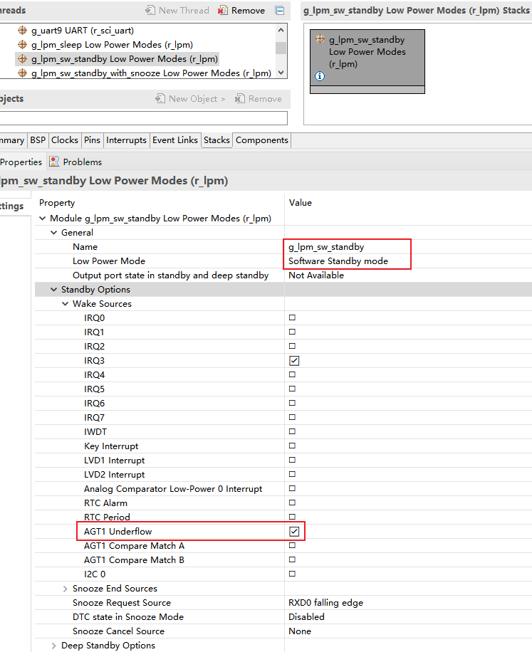
Software Standby Mode
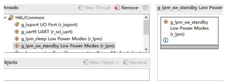
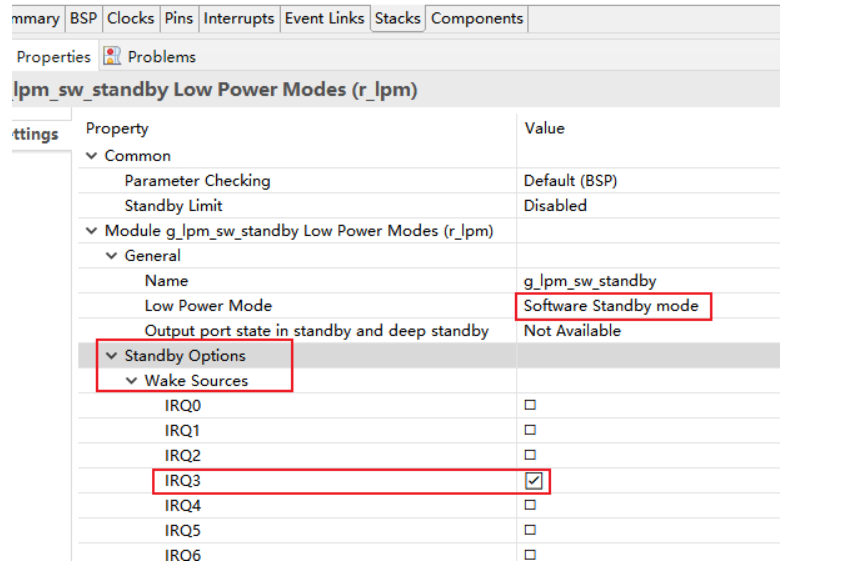
Change Name to g_lpm_sw_standby. Select Software Standby mode for Low Power Mode.
Additionally, in this mode, it is necessary to configure the interrupt source that wakes up the MCU, as AGT1 will be used as the low power timer, so the AGT1 interrupt needs to be checked. If other interrupt sources are needed to wake the MCU in this mode, check the corresponding options.
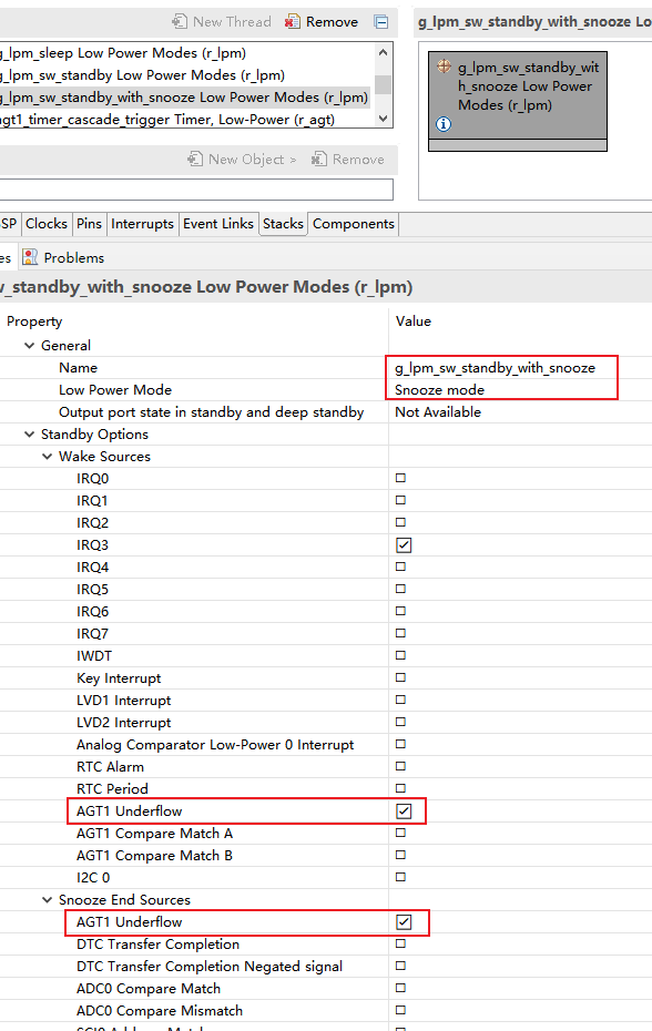
Snooze Mode
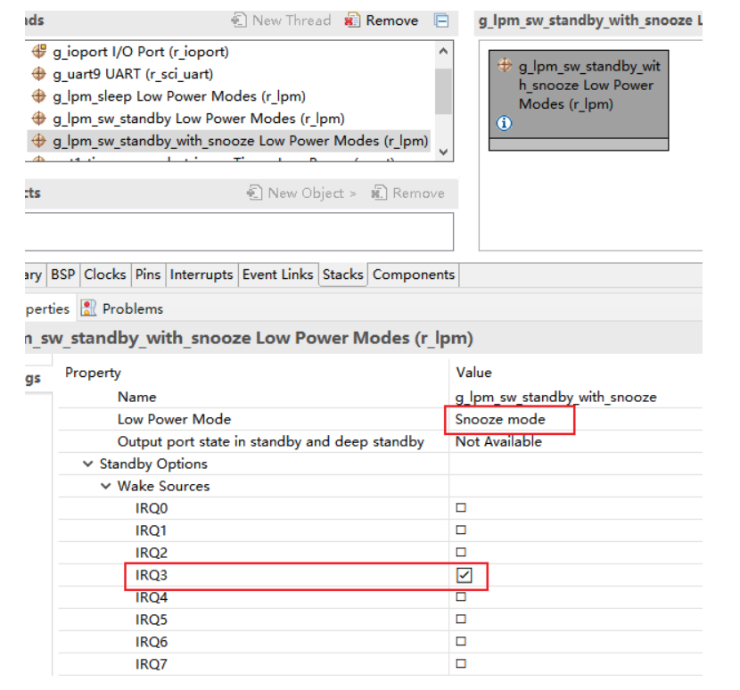
Change Name to g_lpm_sw_standby_with_snooze. Select Snooze mode for Low Power Mode.
In this mode, it is also necessary to configure the interrupt source that wakes up the MCU, as AGT1 will be used as the low power timer, so the AGT1 interrupt needs to be checked. If other interrupt sources are needed to wake the MCU in this mode, check the corresponding options.
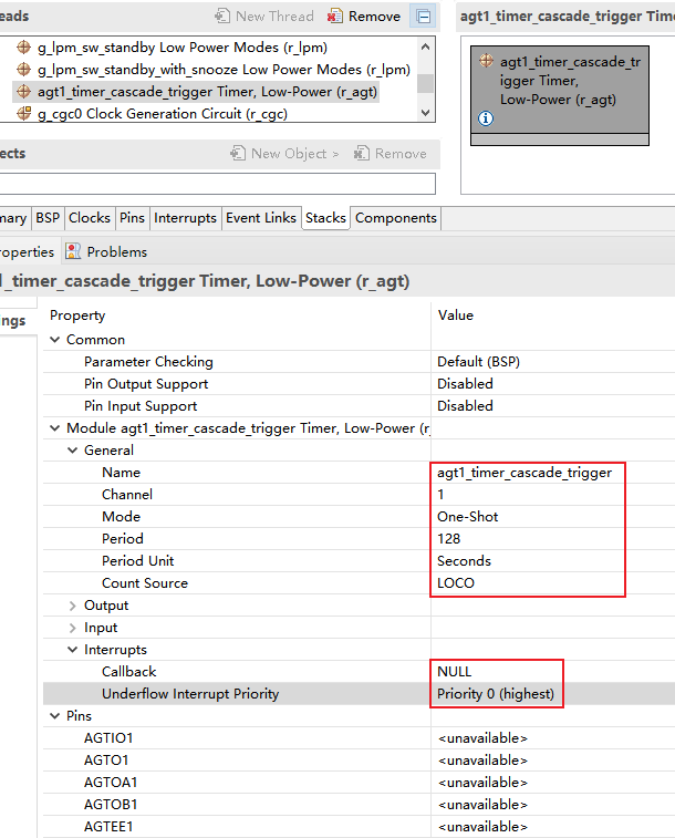
AGT1 Low Power Timer
The AGT1 of the MCU is used as the low power timer of the PM component in the driver, for system clock compensation in the sleep state.
After completing the above configuration steps, the related configurations for the LPM low power mode have been completed. Then configure other peripherals according to the functionality to be achieved in the application.
Low Power DEMO
The above text introduced how to configure different modes of LPM on the RA2L1 of RT-Thread. Next, we will use a small DEMO to verify the operation of the MCU in various modes.
The functionality to be achieved by the low power DEMO is to switch between different low power modes using the S1 button on the CPK-RA2L1 development board, and print the mode-switching prompt information in msh. To achieve this functionality, it is necessary to add a low power wake-up source based on the previous setup.
Add Configuration
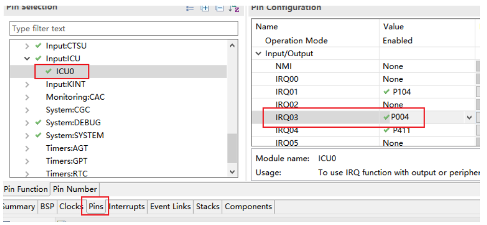
-
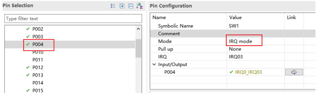
Create an IRQ interrupt, select channel 3 for the IRQ interrupt, with detailed configuration as follows.
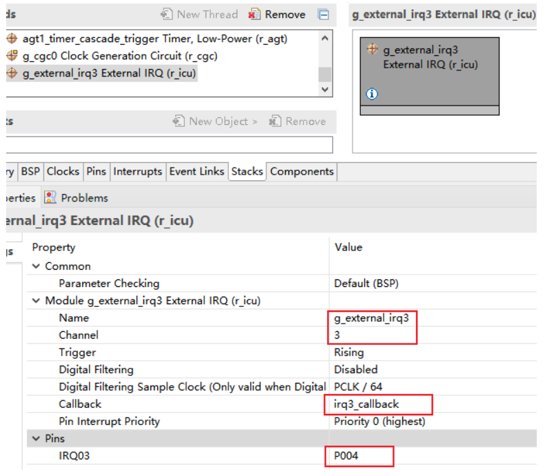
-
Add the IRQ3 wake-up source in the previous configurations for Snooze and Standby modes
-
Then save and generate the configuration code.
Add Test Code
#include <rtthread.h>
#ifdef BSP_USING_LPM
#include <rtdevice.h>
#include <board.h>
#include <drivers/pm.h>
#define WAKEUP_APP_THREAD_STACK_SIZE        512
#define WAKEUP_APP__THREAD_PRIORITY         RT_THREAD_PRIORITY_MAX / 3
#define WAKEUP_EVENT_BUTTON                 (1 << 0)
static rt_event_t wakeup_event;
#define USER_INPUT  "P004"
#define LED2_PIN    "P501" /* Onboard LED pins */
void rt_lptimer_init(rt_lptimer_t  timer,                   const char *name,                   void (*timeout)(void *parameter),                   void       *parameter,                   rt_tick_t   time,                   rt_uint8_t  flag);
rt_err_t rt_lptimer_detach(rt_lptimer_t timer);
rt_err_t rt_lptimer_start(rt_lptimer_t timer);
rt_err_t rt_lptimer_stop(rt_lptimer_t timer);
rt_err_t rt_lptimer_control(rt_lptimer_t timer, int cmd, void *arg);
static struct rt_lptimer lptimer;
static void timeout_cb(void *parameter){    rt_interrupt_enter();    rt_kprintf("\n lptimer callback \n");    rt_interrupt_leave();}
static void lptimer_init(void){    rt_lptimer_init(&lptimer,                    "lpm",                    timeout_cb,                    (void*)&wakeup_event,                    1000,                    RT_TIMER_FLAG_PERIODIC);}
static void lptimer_stop(void){    rt_lptimer_stop(&lptimer);}
static void lptimer_start(void){    rt_lptimer_start(&lptimer);}
static void led_app(void){    static uint8_t key_status = 0x00;    rt_uint32_t led2_pin = rt_pin_get(LED2_PIN);
    rt_pin_write(led2_pin, PIN_HIGH);    switch(key_status%4)    {    case 0:/* IDLE */    lptimer_stop();        rt_pm_release(PM_SLEEP_MODE_NONE);        rt_kprintf("\trequest:IDLE\n");        rt_pm_request(PM_SLEEP_MODE_IDLE);        break;    case 1:/* DEEP */    lptimer_stop();    lptimer_start();        rt_pm_release(PM_SLEEP_MODE_IDLE);        rt_kprintf("\trequest:DEEP\n");        rt_pm_request(PM_SLEEP_MODE_DEEP);        break;    case 2:/* STANDBY */    lptimer_stop();    lptimer_start();        rt_pm_release(PM_SLEEP_MODE_DEEP);        rt_kprintf("\trequest:STANDBY\n");        rt_pm_request(PM_SLEEP_MODE_STANDBY);        break;    case 3:/* NONE */    lptimer_stop();        rt_pm_release(PM_SLEEP_MODE_STANDBY);        rt_kprintf("\trequest:NONE\n");        rt_pm_request(PM_SLEEP_MODE_NONE);        break;    default:        break;    }
    key_status++;    rt_pin_write(led2_pin, PIN_LOW);}
static void wakeup_callback(void* p){    rt_event_send(wakeup_event, WAKEUP_EVENT_BUTTON);}
void wakeup_sample(void){    /* init */    rt_uint32_t pin = rt_pin_get(USER_INPUT);    rt_kprintf("\n pin number : 0x%04X \n", pin);    rt_err_t err = rt_pin_attach_irq(pin, PIN_IRQ_MODE_RISING, wakeup_callback, RT_NULL);    if (RT_EOK != err)    {        rt_kprintf("\n attach irq failed. \n");    }    err = rt_pin_irq_enable(pin, PIN_IRQ_ENABLE);    if (RT_EOK != err)    {        rt_kprintf("\n enable irq failed. \n");    }}
static void wakeup_init(void){    wakeup_event = rt_event_create("wakup", RT_IPC_FLAG_FIFO);    RT_ASSERT(wakeup_event != RT_NULL);    wakeup_sample();}
static void pm_mode_init(void){    rt_pm_release_all(RT_PM_DEFAULT_SLEEP_MODE);    rt_pm_request(PM_SLEEP_MODE_NONE);}
void pm_test_entry(void* para){    /* Wake-up callback function initialization */  wakeup_init();
    /* Power management initialization */    pm_mode_init();
  lptimer_init();
    while (1)    {        /* Wait for wake-up event */        if (rt_event_recv(wakeup_event,                            WAKEUP_EVENT_BUTTON,                            RT_EVENT_FLAG_AND | RT_EVENT_FLAG_CLEAR,                            RT_WAITING_FOREVER, RT_NULL) == RT_EOK)        {            led_app();        }    }}
int pm_test(void){
    rt_thread_t tid = rt_thread_create(            "pmtest",pm_test_entry,RT_NULL,512,10,10);    if(tid)        rt_thread_startup(tid);
    return 0;}
MSH_CMD_EXPORT(pm_test, pm_test);// INIT_APP_EXPORT(pm_test);#endif
Adding the DEMO code to the project can be done by directly adding it to hal_entry.c or creating a new source file.
Testing and Verification
Then compile and download. Connect the development board to the serial tool and enter the command <span>pm_test</span> to start the test DEMO.
Press the S1 button to switch working modes. In DEEP and STANDBY modes, the low power timer will be activated, and when the timer wakes up, it will print the callback interface prompt information.
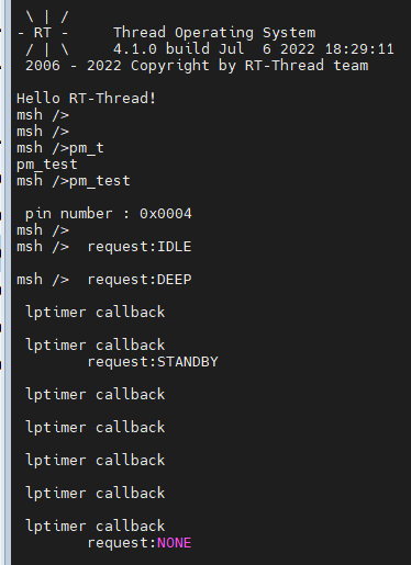
Tests have shown:
(1) Inputting “pm_test” in the serial terminal, the current fluctuated between 8.6mA and 5.8mA.
(2) After pressing S1, the printed information in the serial terminal was “request IDLE“, at which point the current was approximately 2.2mA.
(3) Pressing S1 again, the printed information was “request DEEP“, with a current of approximately 1593uA, and an lptimer interrupt was generated at intervals.
(4) Pressing S1 again, the printed information was “request STANDBY“, with a current of approximately 2.4uA, and an lptimer interrupt was generated at intervals.
(5) Pressing S1 again, the printed information was “request NONE“, returning to the current value of (1), and this process can be executed in a loop.
END