This tutorial introduces the ros_arduino_bridge open source package. If you are creating a ROS mobile robot based on Arduino, this package provides a complete software solution. The package not only controls the motors to drive the chassis but also includes data acquisition from ultrasonic sensors and infrared distance sensors, as well as various general analog and digital signal sensors. It can control the output of digital signals and supports PWM servo control.
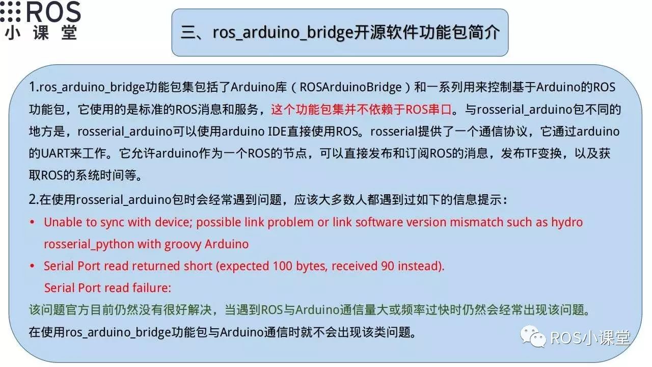
Many of you may have encountered the error message in red in the picture above when using rosserial_arduino. Now, when I think about running:
rosrun rosserial_python serial_node.py /dev/ttyACM0
I always feel unstable and various prompt errors may occur. Currently, the official solution is not very good. Since encountering the ros_arduino_bridge package, it has not only provided us with new ideas to solve this problem but also expanded our control methods for Arduino boards using ROS.
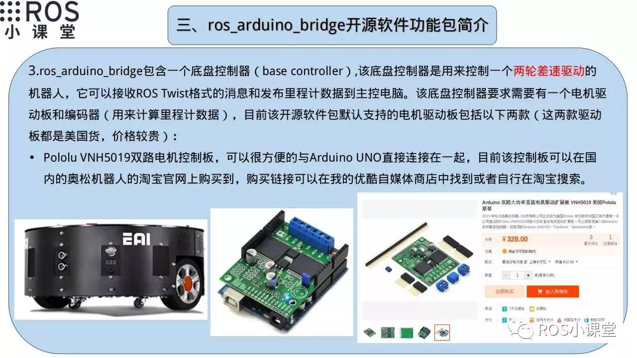
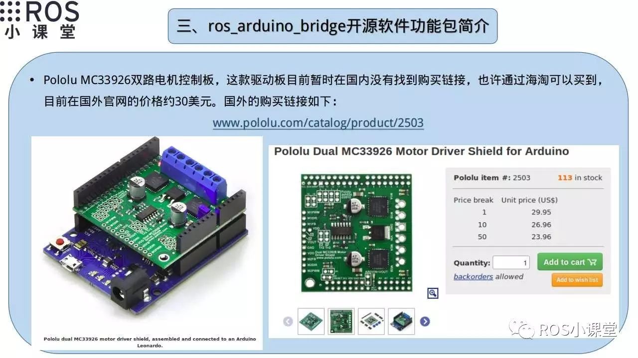
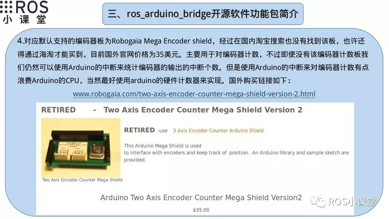
Although this package is designed for two-wheeled differential drive mobile chassis, as long as we put in the effort, we can easily modify this package to drive a three-wheeled omnidirectional mobile chassis. Here, we only need to utilize the software architecture of this package and make slight modifications to achieve our goal.
As for the officially supported hardware, including motor driver boards and encoder counting boards, I do not recommend using them because they are slightly expensive and seem inconvenient to purchase domestically. Therefore, we should take the essence and discard the dross, and we can achieve our goals using various inexpensive motor driver boards available in our country. For encoder counting, we can also use Arduino interrupts or hardware counters to achieve pulse counting functionality.
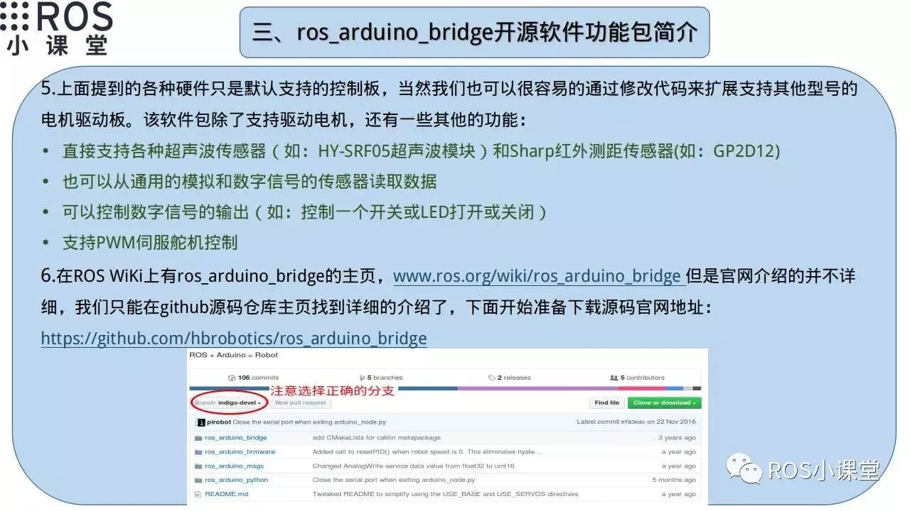
Introducing other functions of the ros_arduino_bridge package, it not only contains a base controller but can also connect various sensors and servo motors to Arduino, showcasing the powerful functionality of this package. Next, we will prepare to download the source code of this package.
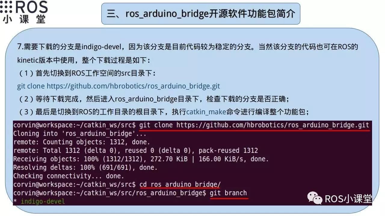
The source code needs to be downloaded to the src directory of the ROS workspace, preferably downloading the indigo-devel branch. After downloading, you can compile it by running catkin_make in the root directory of the workspace.
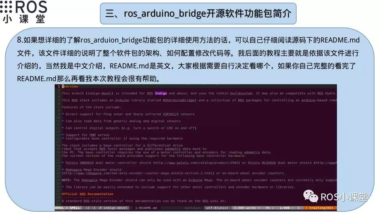 To gain a detailed preliminary understanding of the entire package, it is best to check the README.md file, which provides a detailed introduction to the architecture of the entire package and how to modify the code and test whether the software on the host and the lower machine is working properly.
The following introduction is basically an excerpt from the README.md for everyone to explain. The upcoming tutorials will provide a more detailed introduction to other parts of the README.md.
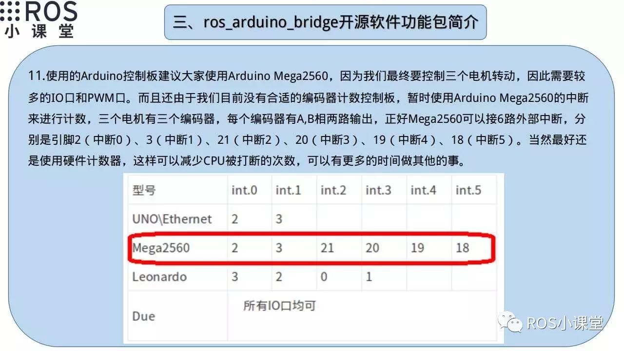
Introducing the selection of Arduino boards, since we have given up the encoder counting board, we can only use the mega 2560 with more IO ports to meet our needs. The 2560 has 6 external interrupts, making it convenient for counting the 6 pulses of three encoders. Of course, besides using interrupts, we can also use hardware counters.
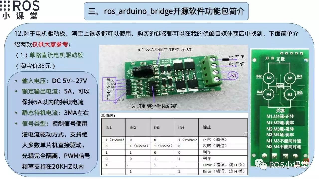
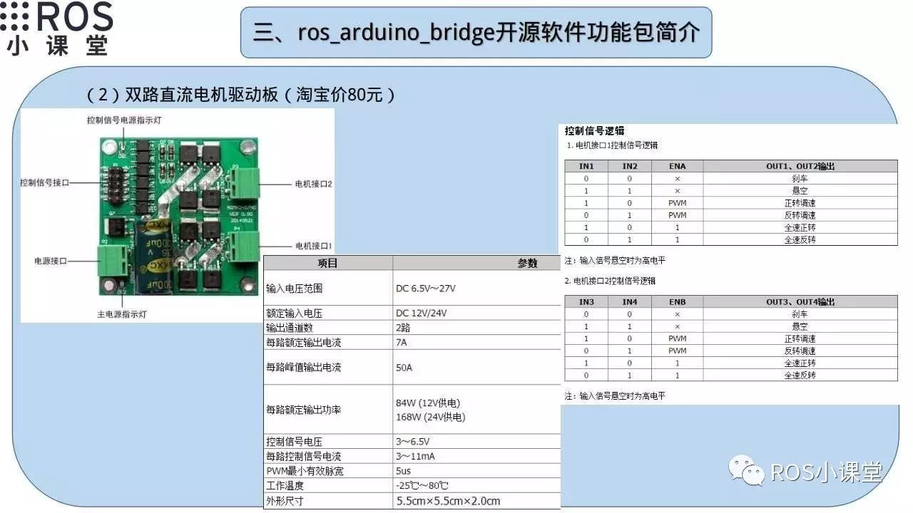
Introducing two models of DC motor driver boards on Taobao with moderate prices, this is for your reference only, and you need to choose the driver board that suits your project needs.
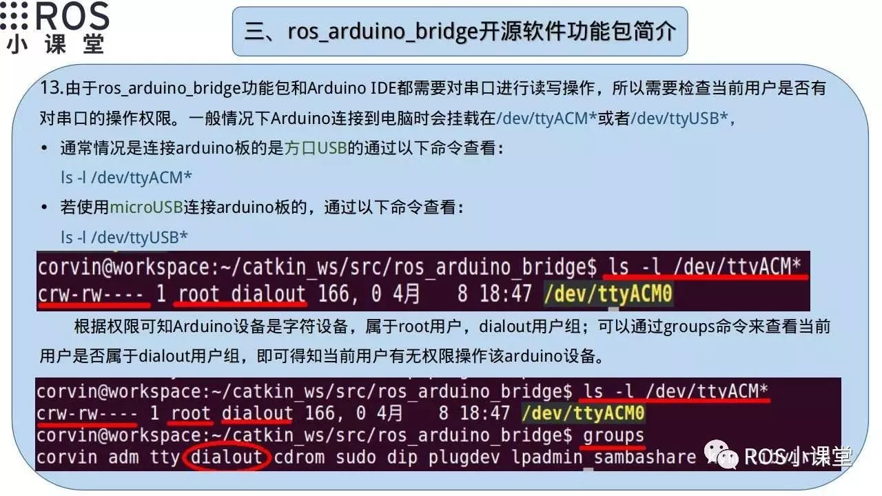
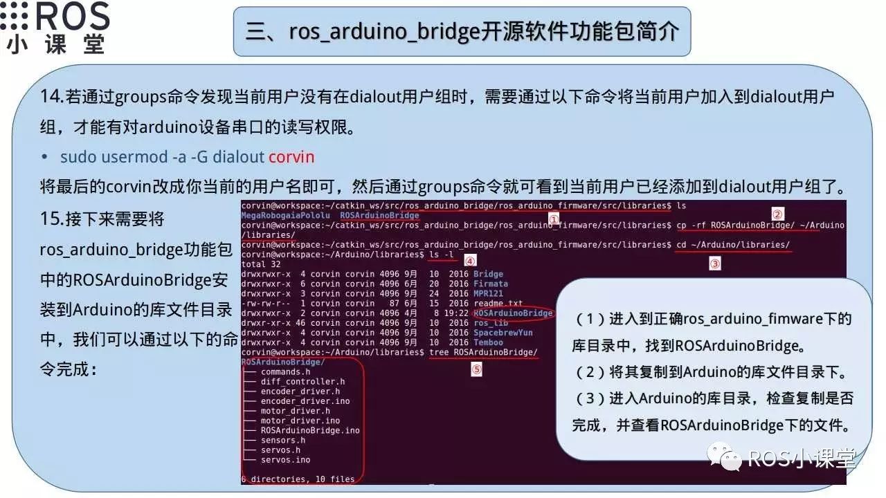
Next, check whether the current user has permission to operate the serial port. You can check whether the current user belongs to the dialout group by using the groups command. If not, you need to add it with the following command:
sudo usermod -a -G dialout current_user
Then you need to copy the ROSArduinoBridge from the source code directory to the Arduino library directory, making it easier for us to view and modify the code.
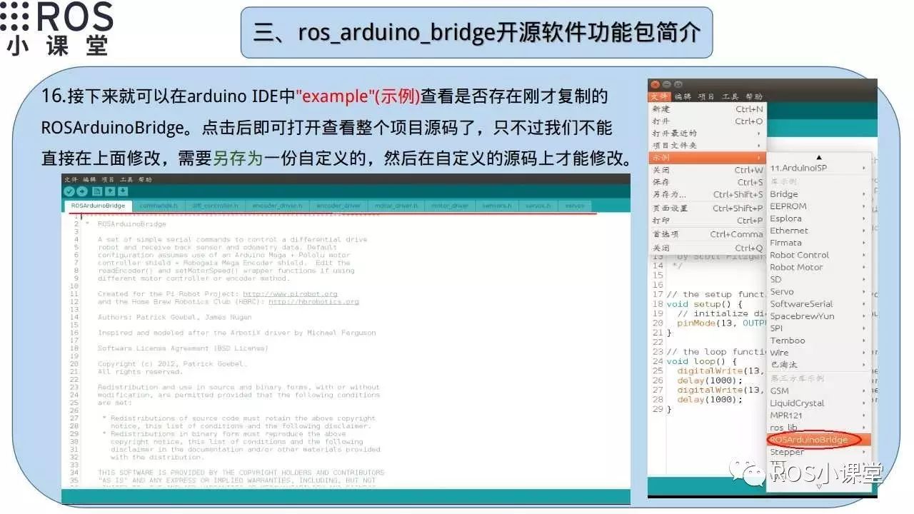
When modifying the ROSArduinoBridge code, you need to save it to your own code directory and not modify the source files. This part of the code is the lower machine code for our mobile chassis, controlled by the Arduino mega2560.
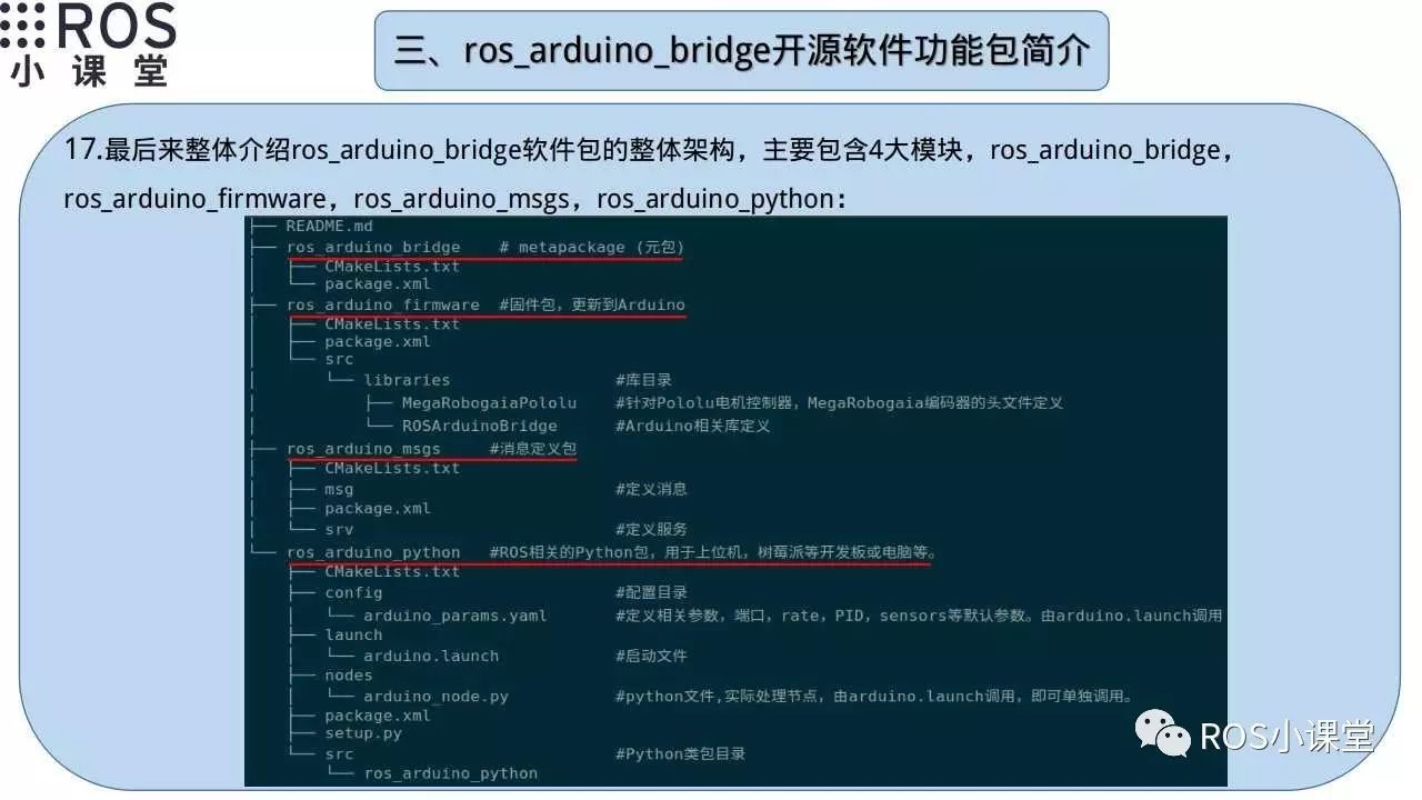
Finally, let’s give an overall introduction to the software architecture of this package, which mainly includes four modules: ros_arduino_bridge, ros_arduino_firmware, ros_arduino_msgs, and ros_arduino_python. Next, we will introduce each module separately.
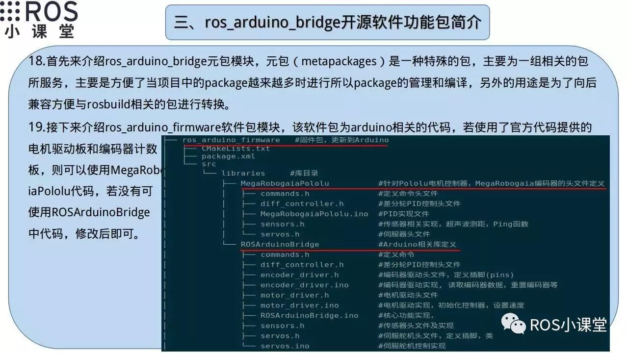
ros_arduino_bridge is a metapackage, and we do not need to modify this module in the future. ros_arduino_firmware is the main code on the lower machine Arduino, and we need to modify this part of the code first to ensure the lower machine can work properly.
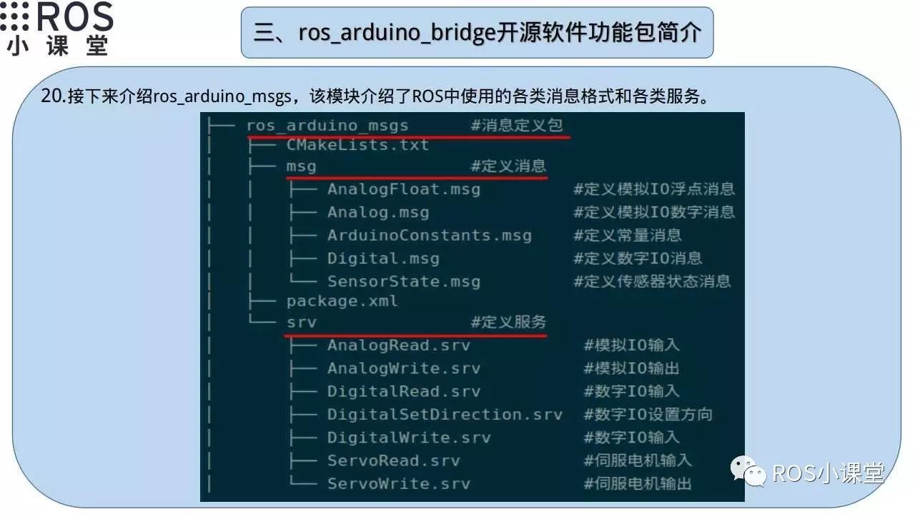
We introduced various messages and services that will be used in the ROS code on the upper machine.
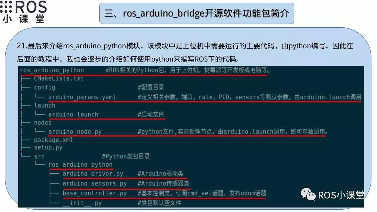
The ros_arduino_python module is the main code for the upper machine ROS, and we will mainly modify this part of the code to ensure the ROS code works properly.
In conclusion, although the ros_arduino_bridge software package is designed for two-wheeled differential drive mobile chassis, we can still use its software architecture to modify it to code for a three-wheeled omnidirectional mobile chassis. If you happen to need a two-wheeled differential drive mobile chassis, using this package basically requires only modifying a few parameters, and the code can be used directly without major modifications. However, it is still best to calibrate the PID parameters for better performance.
Due to my limited ability, if there are any issues in this tutorial, please leave me a message, and I will correct any errors in the tutorial promptly. Similarly, if you want to view the video tutorial for this tutorial, you can search for “ROS Classroom” on Youku to find the corresponding playlist “Making ROS Three-Wheeled Omnidirectional Mobile Chassis” to see the video explanation for this tutorial.