Part.0
Introduction: Why Do We Need Interrupts?

Imagine you are reading a book at home, but you also need to pay attention to visitors. At this moment, you have two options:
Polling: Every few minutes, you put down the book to check at the door if someone is there – this is inefficient and prevents you from focusing on reading.
Interrupt: You concentrate on reading until you hear a knock on the door (interrupt request), you mark your current reading position (save state), go to open the door (execute interrupt service routine), and after handling it, you return to continue reading (restore state).
In the world of STM32, the ARM core needs to efficiently execute the main program while being able to immediately respond to external events (such as timer expiration, data received via serial port, button presses) or internal emergency events. This is the purpose of interrupts – to achieve real-time response and improve system efficiency.
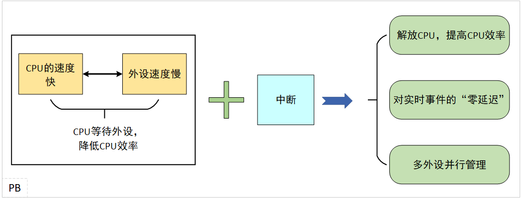
Figure 1. Interrupt Functionality Diagram
Part.1
Core Components of the STM32 Interrupt System
The STM32 is based on the ARM Cortex-M core, where the interrupt system is very powerful and complex. The core components of the interrupt system are shown in Figure 2:
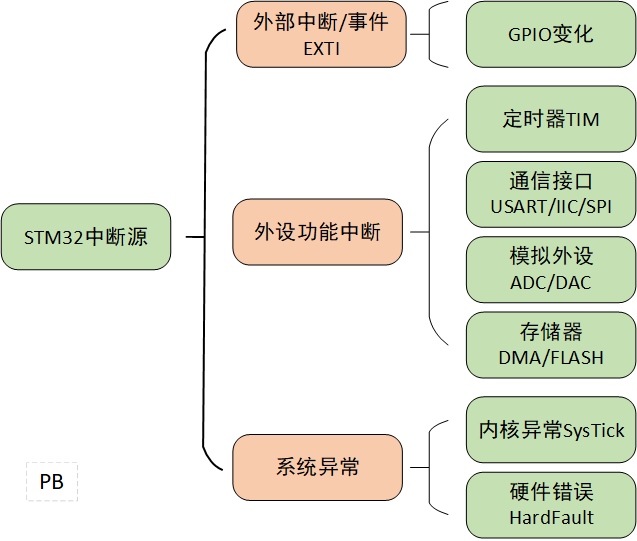 Figure 2. Core Components of the Interrupt System
1.1, Interrupt Source
The interrupt sources in STM32 are hardware signal generators that trigger the CPU to pause the current task and switch to executing emergency events. The three core types are shown in the figure.
Figure 3. STM32 Interrupt Sources
External Interrupt: Level changes from GPIO pins (rising edge, falling edge, both edges).
Internal Peripheral Interrupt: Timers (TIM – overflow, compare match, capture), serial ports (USART/UART – transmission complete, reception ready), analog-to-digital converters (ADC – conversion complete), direct memory access (DMA – transfer complete/half transfer), I2C, SPI, and almost all on-chip peripherals.
Internal Events: System exceptions (such as SysTick timer interrupt, HardFault error, etc.).
1.2, Nested Vectored Interrupt Controller (NVIC)
The NVIC is the “traffic controller” of the STM32 interrupt system, located within the Cortex-M core.
// NVIC structure typedef struct{ uint8_t NVIC_IRQChannel; // Interrupt channel number uint8_t NVIC_IRQChannelPreemptionPriority; // Preemption priority uint8_t NVIC_IRQChannelSubPriority; // Response priority FunctionalState NVIC_IRQChannelCmd; // Enable or disable interrupt} NVIC_InitTypeDef;The responsibilities of the NVIC interrupt controller include:
-
Enable/Disable Interrupts: Control which interrupt sources can issue requests.
-
Priority Management: Assign priorities to each interrupt source (preemption priority and sub-priority).
-
Interrupt Pending and Activation: Receive interrupt requests, determine if their priority is higher than the currently executing code (including the interrupted interrupt service routine), and decide whether to respond immediately.
-
Vector Table Jump: After determining the highest priority pending interrupt, automatically jump to the corresponding interrupt service routine (ISR) entry address.
-
Interrupt Nesting: Allow high-priority interrupts to interrupt low-priority interrupts that are currently executing.
1.3, Interrupt Service Routine (ISR)
The ISR is a function written by the user specifically to handle specific interrupt events. The written interrupt service function should be executed as quickly as possible to avoid blocking other interrupts or the main program. High time-consuming operations should be placed in the main loop or triggered by flags, and access to shared variables between ISR and other programs must use critical section protection to prevent data races.
1.4, Vector Table
The interrupt vector table is a set of special addresses in the processor that stores the entry addresses of each interrupt service routine, usually stored in an address array at the start of Flash (typically at 0x00000000 or 0x08000000). Each entry (vector) corresponds to the ISR entry address for a specific exception or interrupt. When responding to an interrupt event, the CPU automatically retrieves the corresponding ISR address from the vector table based on the interrupt number and jumps to execute it.
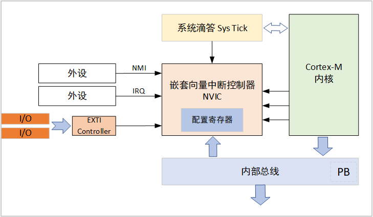
Figure 4. Cortex-M Interrupt Path Diagram
Part.2
Detailed Interrupt Handling Process
2.1, Interrupt Occurrence
When a peripheral (such as a timer overflow) or event source meets the conditions, it sets its “interrupt request” flag.
2.2, NVIC Arbitration
-
NVIC detects the interrupt request.
-
Check if the interrupt is enabled (not masked).
-
Compare the priority of the interrupt with the current CPU execution state (current priority).
-
If the new interrupt priority is higher (higher preemption priority, or the same preemption priority but higher sub-priority and currently allows nesting), the NVIC will suspend the current execution flow.
2.3, Hardware Context Saving
-
The CPU automatically pushes key registers (such as PC program counter, xPSR program status register, LR link register) onto the current stack.
-
Update LR to a special value (such as 0xFFFFFFF1), indicating that the hardware saved context needs to be restored after returning.
-
Update PSR and PC.
2.4, Jump to Execute ISR
The CPU jumps to the ISR corresponding to the interrupt based on the interrupt number retrieved from the vector table.
2.5, Execute User ISR Code
-
Software usually clears the peripheral interrupt request flag at the beginning of the ISR (to prevent re-entry), unless the flag is automatically cleared by hardware.
-
Execute processing logic (such as reading the serial port receive data register, updating the timer counter, setting software flags).
2.6, Interrupt Return
-
After the ISR execution is complete, execute a specific return instruction.
-
The CPU detects the special LR value, triggering the interrupt return sequence.
-
Hardware restores context, and the CPU automatically pops the previously pushed registers to restore the execution state before the interrupt.
2.7, Resume Main Program Execution
The CPU continues executing the interrupted code (main program or low-priority ISR).
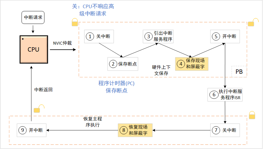 Figure 5. Interrupt Handling Process Diagram
Part.3
Interrupt Priority: Preemption and Nesting
3.1, Preemption Priority
Determines whether one interrupt can interrupt another currently executing interrupt. The lower the value, the higher the priority. High preemption priority interrupts can interrupt low preemption priority interrupts.
| Interrupt Source | Preemption Priority | Description |
| SysTick | 0 | System heartbeat, highest priority |
| Usartx_IRQ | 1 | Higher priority for serial communication |
| IIC/DMA | 2 | Hardware communication interface |
| TIMx | 3 | General timer interrupt |
| EXTI | 4 | External I/O interrupt |
3.2, Subpriority
Subpriority, also known as response priority, determines the processing order when multiple interrupts with preemption priority are pending simultaneously. The lower the value, the higher the priority. Subpriority cannot cause interrupt nesting. The STM32 library functions allow selection between “priority grouping”; for example, if group mode is selected as Group2, it will have 2 bits for preemption priority and 2 bits for response priority.
| Grouping Mode | Preemption Priority Bits | Response Priority Bits |
| Group0 | 0 | 4 |
| Group1 | 1 | 3 |
| Group2 | 2 | 2 |
| Group3 | 3 | 1 |
| Group4 | 4 | 0 |
3.3, Priority Grouping
By setting the PRIGROUP field in the SCB->AIRCR register, you can determine how many bits are allocated for preemption priority and subpriority (a total of 4 bits for priority configuration), i.e., the “bit width allocation” of the priority.
// Set NVIC // NVIC_PreemptionPriority: Preemption priority // NVIC_SubPriority: Response priority // NVIC_Channel: Interrupt number // NVIC_Group: Interrupt group 0~4 // The principle of NVIC_SubPriority and NVIC_PreemptionPriority is that the smaller the value, the higher the priority void MY_NVIC_Init(u8 NVIC_PreemptionPriority,u8 NVIC_SubPriority,u8 NVIC_Channel,u8 NVIC_Group) { u32 temp; MY_NVIC_PriorityGroupConfig(NVIC_Group); // Set group, call the function written above temp=NVIC_PreemptionPriority<<(4-NVIC_Group); // Preload preemption priority into NVIC_IPX[]'s [7:4] bits, preemption priority comes first temp|=NVIC_SubPriority&(0x0f>>NVIC_Group); // Preload response priority into NVIC_IPX[]'s [7:4] bits, response priority comes later temp&=0xf; // Take the lower four bits NVIC->ISER[NVIC_Channel/32]|=(1<<NVIC_Channel%32); // Enable interrupt bit (to clear, just do the opposite operation) NVIC->IP[NVIC_Channel]|=temp<<4; // Set response priority and preemption priority}Interrupt priority grouping: STM32 supports different interrupt priority grouping methods, including a total of 5 modes from 0 to 4. The number of preemption and response priorities varies in each mode. Choosing the appropriate grouping mode is crucial for optimizing system performance. For example, Group 4 (lowest preemption priority, highest response priority) may be more suitable for task scheduling scenarios that require fine control.
Part.4
STM32 Interrupt Programming Steps
The steps for STM32 interrupt programming are as follows:
-
Configure the peripheral itself: Initialize the peripheral (such as timers, serial ports) and enable its ability to generate interrupts;
-
Configure the interrupt source (EXTI – if it is a GPIO interrupt);
-
Configure NVIC;
-
Write the interrupt service routine (ISR)
Following the above programming steps, write the project code for sending and receiving data via serial interrupt.
// Code section // Configure the peripheral itself // Configure the interrupt source void USART_Config1(void){ GPIO_InitTypeDef GPIO_InitStructure; USART_InitTypeDef USART_InitStructure; // Enable the clock for the serial port GPIO DEBUG_USART_GPIO_APBxClkCmd(DEBUG_USART_GPIO_CLK, ENABLE); // Enable the clock for the serial port peripheral DEBUG_USART_APBxClkCmd(DEBUG_USART_CLK, ENABLE); // Configure USART Tx GPIO as push-pull alternate function mode GPIO_InitStructure.GPIO_Pin = DEBUG_USART_TX_GPIO_PIN; // pin2 GPIO_InitStructure.GPIO_Mode = GPIO_Mode_AF_PP; GPIO_InitStructure.GPIO_Speed = GPIO_Speed_50MHz; GPIO_Init(DEBUG_USART_TX_GPIO_PORT, &GPIO_InitStructure); // Configure USART Rx GPIO as floating input mode GPIO_InitStructure.GPIO_Pin = DEBUG_USART_RX_GPIO_PIN; // pin3 GPIO_InitStructure.GPIO_Mode = GPIO_Mode_IN_FLOATING; GPIO_Init(DEBUG_USART_RX_GPIO_PORT, &GPIO_InitStructure); // Configure serial port working parameters // Configure baud rate USART_InitStructure.USART_BaudRate = DEBUG_USART_BAUDRATE; // Configure frame data length USART_InitStructure.USART_WordLength = USART_WordLength_8b; // Configure stop bits USART_InitStructure.USART_StopBits = USART_StopBits_1; // Configure parity bit USART_InitStructure.USART_Parity = USART_Parity_No; // Configure hardware flow control USART_InitStructure.USART_HardwareFlowControl = USART_HardwareFlowControl_None; // Configure working mode, receive and transmit together USART_InitStructure.USART_Mode = USART_Mode_Rx | USART_Mode_Tx; // Complete the serial port initialization configuration USART_Init(DEBUG_USARTx, &USART_InitStructure); // Serial port interrupt priority configuration NVIC_Configuration1(); // Enable serial port receive interrupt USART_ITConfig(DEBUG_USARTx, USART_IT_RXNE, ENABLE); // Enable the serial port USART_Cmd(DEBUG_USARTx, ENABLE); } // Configure NVIC static void NVIC_Configuration1(void){ NVIC_InitTypeDef NVIC_InitStructure; /* Nested Vectored Interrupt Controller group selection */ NVIC_PriorityGroupConfig(NVIC_PriorityGroup_2); /* Configure USART as interrupt source */ NVIC_InitStructure.NVIC_IRQChannel = DEBUG_USART_IRQ; /* Preemption priority */ NVIC_InitStructure.NVIC_IRQChannelPreemptionPriority = 1; /* Sub-priority */ NVIC_InitStructure.NVIC_IRQChannelSubPriority = 1; /* Enable interrupt */ NVIC_InitStructure.NVIC_IRQChannelCmd = ENABLE; /* Initialize NVIC configuration */ NVIC_Init(&NVIC_InitStructure);} // Write interrupt service routine ISR void DEBUG_USART_IRQHandler(void){ if(USART_GetITStatus(DEBUG_USARTx, USART_IT_RXNE) != RESET) { // Save serial port data CommBuff[TalNum++]=USART_ReceiveData(DEBUG_USARTx); rxd_flag=1; // Set the status of serial port 1 to one // Clear the serial port interrupt flag USART_ClearITPendingBit(DEBUG_USARTx, USART_IT_RXNE); }}Part.5
Common Issues and Pitfalls with Interrupts
 In STM32 embedded development, the interrupt system is the core of real-time response, but it is also a frequent source of faults. Conflicts in NVIC priority configuration can block critical events, and excessive interrupt nesting can lead to stack overflow and memory violations. Understanding the interaction chain of conflicts is key to stable development. Below are common issues and pitfalls.Keep ISR Short:Long blocking in ISR can lead to missing other interrupts, resulting in lost interrupts or sluggish system response.Clear Interrupt Flags Promptly:Clear the corresponding interrupt flag immediately at the start of the ISR or after confirming the interrupt source; otherwise, it may lead to continuous triggering of interrupts (“interrupt storm”).Be Cautious with Shared Data Access:When communicating between ISR and the main program through global variables, critical section protection or semaphores must be used.Critical Section Protection: Disable interrupts before accessing shared variables and re-enable them immediately after.Semaphore: Use semaphores provided by RTOS to control access to shared resources, ensuring that only one task accesses these shared resources at a time.Lock-Free Data Structures: Such as circular buffers (commonly used for serial reception).Avoid Calling Non-Reentrant Functions in ISR:For example, some library functions (like printf in standard implementations) are usually non-reentrant and time-consuming. When using non-reentrant functions, ensure they are not interrupted by other interrupts. You can disable interrupts or use other protection mechanisms when using non-reentrant functions in interrupt handlers.Set Interrupt Priorities Reasonably:Assign reasonable priorities to each interrupt source based on application requirements. Generally, interrupts with high real-time requirements should be assigned higher preemption priorities; related interrupts (like multiple serial ports) can be set to the same preemption priority and distinguished by sub-priority; avoid unnecessarily high priorities to prevent low-priority tasks from being starved.Be Aware of Interrupt Nesting Depth:Deep nesting consumes more stack space (hardware pushes onto the stack each time it nests), ensure sufficient stack space to prevent data overflow.
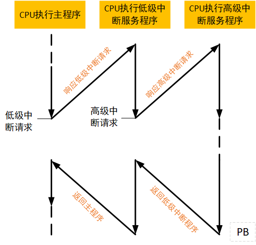 Figure 6. Interrupt Nesting Process Diagram
Part.6
Interrupt vs Polling
While interrupts have many advantages, polling also has its applications. A good engineer can choose the optimal solution among many options based on real-time requirements, resource constraints, and system objectives.
| Feature | Interrupt | Polling |
| Response Speed | Extremely fast, immediate response when events occur | Slow and uncertain, depends on polling frequency |
| CPU Usage | CPU is occupied only when events occur, high efficiency when idle | Continuously occupies CPU to check status, low efficiency |
| Real-Time Performance | High, suitable for events with strict timing requirements | Low, response delay depends on polling interval |
| Implementation Complexity | Relatively high, requires NVIC configuration, writing ISR, handling shared data | Simple, just loop to check flags |
| Applicable Scenarios | Key detection, communication reception | Simple tasks, infrequent state changes |
Conclusion:For scenarios requiring rapid response, high real-time requirements, or low event occurrence frequency (such as button presses), interrupts are the first choice. For simple, non-real-time tasks or tasks with plenty of CPU idle time, polling may be simpler.
Part.7
Summary
The interrupt mechanism of STM32 is the cornerstone of its ability to achieve real-time, multi-task processing. A deep understanding of NVIC, priority management, interrupt handling processes, and best practices for writing ISRs is key skills for developing efficient and reliable embedded systems. Mastering interrupts will enable your STM32 applications to respond to critical events with lightning speed while maximizing CPU utilization. Thank you for reading.