In-Depth Guide to Embedded Linux Network Interface Design

In-Depth Guide to Embedded Linux Network Interface Design

In embedded Linux, networking is a commonly used feature, especially in fields like industrial control and the Internet of Things. Today, we will learn about the design of network interfaces in embedded Linux!

Introduction to Embedded Networking

Network Hardware Interfaces in Embedded Systems

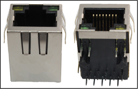
When we mention networking, the hardware that usually comes to mind is the “network card.” Nowadays, the network card is typically accomplished through a chip. Embedded network hardware is divided into two parts: MAC and PHY. People generally refer to the datasheet to determine whether a SOC supports networking. If a chip’s datasheet states that it supports networking, it usually means that this SOC has an integrated MAC, which is similar to peripherals like the I2C controller or SPI controller. However, having just a MAC is not sufficient to drive a network; another chip, the PHY, is also required. Therefore, for SOCs with an integrated MAC, an external PHY chip must be paired. For SOC chips without an internal MAC, an external MAC + PHY integrated chip is needed, leading us to two common embedded network hardware solutions.

1.SOC Without an Internal Network MAC Peripheral

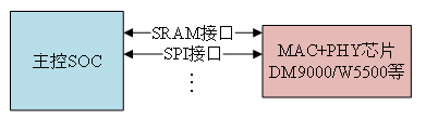
For SOC chips without an internal MAC, external MAC + PHY integrated network chips can be used to achieve network functionality. For example, the DM9000 is commonly used in Samsung Linux development boards, providing an SRAM interface to the SOC, which operates the DM9000 in SRAM mode.

Some external network chips are even more powerful, integrating a hardware TCP/IP protocol stack and providing an SPI interface, such as the W5500. This is generally used in microcontroller applications, where the microcontroller communicates with the W5500 via the SPI interface. Since the W5500 has a built-in hardware TCP/IP protocol stack, the microcontroller does not need to port a software protocol stack and can directly operate the W5500 through SPI, simplifying the microcontroller’s networking solution.

The advantage of this solution is that it allows SOCs that do not support networking to find alternative ways to achieve network functionality. However, the downside is that network efficiency is not high since typically, chips with integrated MACs have network acceleration engines, such as dedicated DMA, which significantly enhance network processing efficiency. Moreover, such chips generally do not support fast networking speeds, usually limited to 10/100M. Additionally, compared to PHY chips, these chips tend to be more expensive with fewer options available.

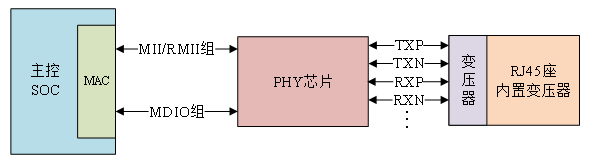
The connection between the SOC and the external MAC + PHY chip is shown in Figure 1-1:

In-Depth Guide to Embedded Linux Network Interface Design
Figure 1-1 Connection between the Main Control SOC and External MAC + PHY Chip
2. SOC with Integrated Network MAC Peripheral
When we say a certain SOC supports networking, we mean it has an internal integrated network MAC peripheral, which still requires an external network PHY chip.
Currently, almost all SOCs that support networking have built-in MAC peripherals, such as the STM32F4/F7/H7 series, and NXP’s I.MX series. The advantages of having an internal integrated network MAC are as follows:
1) Internal MAC peripherals typically have dedicated acceleration modules, such as dedicated DMA, which accelerate the processing of network data.
2) Fast networking speeds, supporting 10/100/1000M speeds.
3) More options for external PHY, leading to lower costs.
The internal MAC peripheral connects to the external PHY chip via MII or RMII interfaces, which are used for transmitting network data. Additionally, the main control unit needs to configure or read the PHY chip, which involves reading and writing to the PHY’s internal registers, necessitating a control interface called MDIO. MDIO is similar to I2C, using two wires: one data line called MDIO and one clock line called MDC.
The connection between the internal MAC peripheral and the external PHY chip is shown in Figure 1-2:
In-Depth Guide to Embedded Linux Network Interface Design
Figure 1-2 Connection between Internal MAC and External PHY
When working on projects requiring networking functionality, it is strongly recommended to choose a main control SOC with an internal integrated network MAC peripheral! The I.MX6ULL has two 10M/100M network MAC peripherals, and the Zedboard ALPHA development board comes with two PHY chips, model LAN8720. Therefore, this chapter will only explain the SOC internal MAC + external PHY chip solution.
MII/RMII Interfaces
Earlier, we discussed that the internal MAC connects to the external PHY chip via MII/RMII interfaces to complete network data transmission. In this section, we will learn about what MII and RMII interfaces are.
1. MII Interface
MII stands for Media Independent Interface, which is defined as the Ethernet standard interface by IEEE-802.3. The MII interface is used for connecting Ethernet MAC to PHY chips, as shown in Figure 1-3:
In-Depth Guide to Embedded Linux Network Interface Design
Figure 1-3 MII Interface
The MII interface has a total of 16 signal lines, which are defined as follows:
TX_CLK: Transmit clock; for a 100M speed, the clock frequency is 25MHz, while for 10M speed, it is 2.5MHz. This clock is generated by PHY and sent to MAC.
TX_EN: Transmit enable signal.
TX_ER: Transmit error signal, active high, indicating that the data transmitted during the TX_ER active period is invalid. TX_ER does not function at 10Mbps speed.
TXD[3:0]: Transmit data signal lines, totaling 4.
RXD[3:0]: Receive data signal lines, totaling 4.
RX_CLK: Receive clock signal; for a 100M speed, the clock frequency is 25MHz, and for 10M speed, it is 2.5MHz. RX_CLK is also generated by PHY.
RX_ER: Receive error signal, active high, indicating that the data transmitted during the RX_ER active period is invalid. RX_ER does not function at 10Mbps speed.
RX_DV: Receive data valid, functioning similarly to TX_EN.
CRS: Carrier sense signal.
COL: Collision detection signal.
The drawback of the MII interface is that it requires too many signal lines, not including the two management interface data lines, MDIO and MDC, thus leading to a decline in MII interface usage.
2. RMII Interface
RMII stands for Reduced Media Independent Interface, which is a simplified version of the MII interface. The RMII interface only requires 7 data lines, directly reducing 9 lines compared to MII, significantly simplifying board wiring. The RMII interface connection to PHY chips is illustrated in Figure 1-4:
In-Depth Guide to Embedded Linux Network Interface Design
Figure 1-4 RMII Interface
TX_EN: Transmit enable signal.
TXD[1:0]: Transmit data signal lines, totaling 2.
RXD[1:0]: Receive data signal lines, totaling 2.
CRS_DV: Equivalent to the combination of RX_DV and CRS signals in the MII interface.
REF_CLK: Reference clock, provided by an external clock source, with a frequency of 50MHz. Unlike MII, where the receive and transmit clocks are independent and provided by the PHY chip, RMII combines these functions.
In addition to MII and RMII, there are other interfaces such as GMII, RGMII, SMII, etc. The specifics of these interfaces are generally similar, so they will not be discussed here. Both network ports on the Zedboard ALPHA development board use RMII interfaces to connect the MAC and external PHY chips.
MDIO Interface
MDIO stands for Management Data Input/Output, which is a simple two-wire serial interface consisting of one MDIO data line and one MDC clock line.Driver programs can access any register of the PHY chip via MDIO and MDC. MDIO supports up to 32 PHYs.At any one time, only one PHY can be operated; how do we distinguish between these 32 PHY chips? Similar to I2C, a device address is used.All PHY chips under the same MDIO interface must have unique device addresses, and the specific values must be checked in the corresponding PHY datasheet.
Thus, when connecting the MAC and external PHY chip, the main interfaces are MII/RMII and MDIO, along with possible additional pins for reset, interrupts, etc.
RJ45 Interface
Network devices are connected via network cables, and the connector for the network cable is called the RJ45 socket, as shown in Figure 1-5:
In-Depth Guide to Embedded Linux Network Interface Design
Figure 1-5 RJ45 Socket
The RJ45 socket must connect to the PHY chip, but a network transformer is needed in between for isolation and filtering. The network transformer is also a chip, typically shaped as shown in Figure 1-6:
In-Depth Guide to Embedded Linux Network Interface Design
Figure 1-6 Network Transformer
However, many RJ45 sockets now integrate network transformers internally. For instance, the commonly used HR911105A is an RJ45 socket with a built-in network transformer. The RJ45 socket with an integrated network transformer has the same pins as a non-integrated one, but the non-integrated socket is generally shorter. Therefore, when designing your board, be sure to consider whether the RJ45 socket you are using has a built-in network transformer. If it does not, you will need to add the network transformer circuit yourself! Similarly, if your designed hardware requires an RJ45 socket with a built-in network transformer, you cannot simply solder a non-integrated RJ45 socket, as this would prevent proper network functionality!
Typically, there are two lights on the RJ45 socket, one yellow (orange) and one green. If the green light is on, it indicates a normal network connection, while if the yellow light is blinking, it signifies ongoing network communication. These two lights are controlled by the PHY chip, which has two pins to connect to the lights on the RJ45 socket. The internal MAC + external PHY + RJ45 socket (with built-in network transformer) constitute a complete embedded network interface hardware, as shown in Figure 1-7:
In-Depth Guide to Embedded Linux Network Interface Design
Figure 1-7 Embedded Network Hardware Interface Diagram
Basic Knowledge of PHY Chips
PHY is a standard module defined by IEEE 802.3. As previously mentioned, the SOC can configure or read the PHY chip’s status, which requires the PHY’s internal registers to implement. The PHY chip’s register address space is 5 bits, with addresses 0-31 totaling 32 registers. IEEE defines the functions of registers 0-15, while registers 16-31 are implemented by manufacturers. This means that regardless of which manufacturer’s PHY chip you use, the functions of registers 0-15 will be identical. These 16 registers are sufficient to drive the PHY chip, at least ensuring basic network data communication. Consequently, the Linux kernel has a generic PHY driver, which theoretically allows any PHY chip to use this driver to verify whether networking is functioning correctly. In practice, however, some issues may arise that prevent the Linux kernel’s generic PHY driver from functioning correctly, necessitating debugging by the driver development team. However, as PHY chip performance continues to improve, the 32 register space may not meet manufacturers’ needs, prompting many manufacturers to adopt paging techniques to extend the register address space to define additional registers. These extra registers can be used to implement manufacturer-specific technologies, meaning that the Linux kernel’s generic PHY driver may not support these unique features, requiring the PHY manufacturer to provide corresponding driver source code. Thus, you will also find many specific PHY chip driver source codes in the Linux kernel. Regardless of how many unique features your PHY chip has, the Linux kernel’s generic PHY driver should suffice for basic network communication, so there is no need to worry about the complexity of writing network drivers when replacing PHY chips.
The “22.2.4 Management functions” section in the original English version of the IEEE802.3 protocol specifies the functions of the first 16 registers, as shown in Figure 1-8:
In-Depth Guide to Embedded Linux Network Interface Design
Figure 1-8 Functions of the First 16 Registers Defined by IEEE
The content regarding these 16 registers is also detailed in the protocol, so it will not be analyzed here. You can refer to a specific PHY chip datasheet to compare the register structures, for example, the commonly used LAN8720A PHY for 100M networks, to see if the initial registers match those in Figure 1-8.
This concludes the discussion on the design of network interfaces in embedded Linux. Do you still have lingering questions, young friends? Actually, all the embedded Linux content discussed above comes from Tsinghua University’s newly publishednew book “Linux Driver Development and Practice.” Zuo Mengzhu’s 2023 new book “Linux Driver Development Practice” is here!
Copyright belongs to the original author
Editor: Liang Jiajia
– Related Recommendations –

In-Depth Guide to Embedded Linux Network Interface Design

↑ Click the image for book discounts ↑
“Detailed Explanation and Practice of Atomic Embedded Linux Driver Development (ARM Linux Driver)”
Author: Zuo Zhongkai
Tsinghua University Press

Content Summary

With the rapid development of semiconductor technology and chip technology, the prices of MPU chips capable of running embedded Linux systems are continuously decreasing. ARM architecture chips are widely used in mobile phones, industrial control, IoT, and autonomous driving. Areas that previously relied heavily on MCUs are now starting to adopt embedded Linux systems. Applications such as card gate machines and automotive charging station operation panels, as well as IoT gateways, all feature embedded Linux, leading to a sharp increase in demand for embedded Linux development talent. Compared to microcontroller development, embedded Linux development is significantly more challenging, particularly in driver development. The embedded Linux kernel is designed with an object-oriented approach and has developed numerous driver frameworks. Developers must master these frameworks to write drivers that meet embedded Linux requirements. This book covers everything from basic LED programs to network driver development, encompassing the three main types of Linux drivers: character device drivers, block device drivers, and network device drivers. A key feature of this book is its comprehensive coverage of device tree development, with the exception of a few initial examples demonstrating how to operate chip registers without using a device tree; all other examples utilize device trees, covering common peripherals in embedded Linux driver development. This book serves as a learning and reference guide for engineers engaged in embedded development, IoT, industrial control, and can also be used as a textbook for courses in computer, electronics, and automation majors related to embedded systems, microcomputer interfaces, and IoT.

In-Depth Guide to Embedded Linux Network Interface Design
#Follow our official video account for more#
#Click the button below to follow us#
Find more like-minded people
In-Depth Guide to Embedded Linux Network Interface Design
In-Depth Guide to Embedded Linux Network Interface Design ShareLike and Watchat least give me one~

Leave a Comment