Skip to content
Today’s electronic devices, ranging from TWS headphones and wearable devices to electric vehicles, rely heavily on lithium-ion or polymer batteries for power. Depending on the power requirements of the electronic devices, a battery pack may consist of multiple battery cells (cells) arranged together. The charging and discharging of the battery pack, as well as the input/output voltage and current states, need to be precisely monitored and measured to ensure safe power supply for the electronic devices. This necessitates a specialized system known as a Battery Management System (BMS) to monitor, calculate, communicate, and protect the battery pack’s operating state.
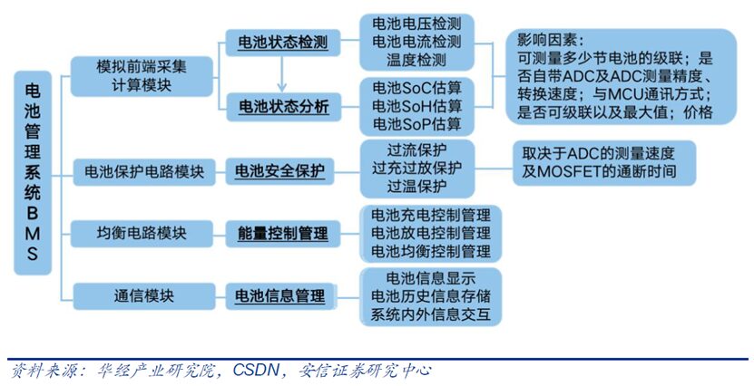
Monitoring: The BMS can monitor various state indicators of the battery pack, including voltage (the voltage of individual cells, total voltage, or specific voltages between the two), temperature (average temperature, temperature of individual cells), input/output current, health status of individual cells, and the balance status of the cells;
Calculation: The BMS can calculate many indicators, including voltage (minimum and maximum cell voltage), State of Charge (SoC) indicating the level of charge, State of Health (SoH) measuring battery capacity, Safety State (SOS), maximum charging current (Charging Current Limit, CCL), maximum discharging current (Discharging Current Limit, DCL), internal resistance that determines open-circuit voltage, total energy provided, total operating time, temperature monitoring, etc.;
Communication: The central controller inside the BMS can communicate with internal hardware and also communicate externally through various methods (such as USB, CAN, or wireless communication protocols);
Protection: The BMS can also provide various protections for the battery to prevent the battery pack’s state from exceeding the Safe Operating Area (SOA), such as overcurrent during charging/discharging, overvoltage during charging/discharging, overheating, overpressure, and current leakage.
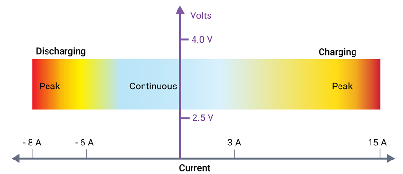
Typical charging and discharging current variation states of lithium batteries. (Source: Synopsys)
The BMS can closely monitor, control, and distribute reliable charging and discharging of the entire battery system throughout its lifespan. Precise monitoring of current and voltage distribution is crucial because overcharging the battery can cause fires or explosions, while undercharging (or complete discharging) can lead to battery failure. The quality of the BMS directly affects the endurance of electronic devices; a high-quality battery management system can significantly extend the overall lifespan of the battery, thereby reducing total ownership costs.
The BMS acts as the “brain” of the lithium-ion battery pack, uniformly monitoring, commanding, and coordinating the cells. In terms of composition, the battery management system includes a Battery Management Integrated Circuit (BMIC), an Analog Front End (AFE), an embedded microprocessor, and embedded software. The BMS implements functions such as voltage protection, temperature protection, short-circuit protection, overcurrent protection, insulation protection, etc., based on real-time collected cell status data and specific algorithms, and achieves voltage balance management between cells and external data communication.
 The Battery Management Integrated Circuit (BMIC) is an important subdivision of power management chips, including charging management chips, battery measuring chips, and battery safety chips. Charging management chips can convert external power sources into suitable charging voltage and current for the cells, and monitor the charging status of the cells in real-time during the charging process, adjusting and controlling the charging voltage and current to ensure safe and efficient charging of the cells. Based on the characteristics of lithium batteries, charging management chips automatically perform pre-charge, constant current charging, and constant voltage charging, effectively controlling the charging state at each stage.
Charging management chips can be divided into switching mode, linear mode, and charge pump mode based on their working modes. Switching mode is highly efficient, suitable for high current applications, and can be flexibly designed as buck, boost, or buck-boost architectures. Common fast charging solutions are usually in switching mode. Linear mode is suitable for low-power portable electronic products, with lower requirements for charging current and efficiency, typically not exceeding 1A, but has higher requirements for size and cost. Charge pump mode can achieve efficiencies of over 97%, but due to architectural reasons, its output voltage is usually in a fixed ratio with the input voltage, and in practical applications, it is usually used in conjunction with switching-type charging management chips.
Charge pump charging management chips use a switched capacitor method for controlling the conversion of charging voltage and current. Compared to general charging management chips, charge pump chips do not require inductors, offering higher efficiency, higher power density, and lower heat generation, and have become one of the mainstream solutions for high-power charging above 22.5W for mobile phones.
In addition, with the popularity of wireless charging for mobile phones, wireless charging management chips have gradually become an important branch of charging management chip products. Wireless charging includes wireless transmitter chips and wireless receiver chips, widely used in wireless charging pads, wireless car chargers, wireless power banks, and mobile phones. The transmitter chip generally includes a Tx analog front end and a Tx embedded chip, supporting a 20W transmission power; the receiver chip is a TRx embedded chip, mainly used in mobile phone receivers, supporting a maximum receiving power of 50W.
The battery measurement chip (battery gauge IC) is mainly used to collect information such as cell voltage, temperature, and current, calculating battery capacity and health information through Coulomb counting and battery modeling, and communicating with external hosts via I2C/SMBUS/HDQ and other communication ports. The gauge IC can be discrete or integrated with battery protection ICs. The primary protection IC can control charge and discharge MOSFETs, with protection actions being recoverable, meaning that when overcharging, over-discharging, overcurrent, short-circuit, and other safety events occur, the corresponding charge and discharge switches will disconnect, and once the safety event is resolved, the switches will automatically reconnect, allowing the battery to continue to be used.
Hardware, algorithms, and firmware are the three core elements of the battery gauge chip. The hardware is used to achieve high-precision sampling and low-power operation; the algorithm is used for battery modeling; and the firmware is used to implement algorithm programming and calculate output capacity information. When selecting a battery gauge chip, it is usually necessary to consider the chemical type of the cell, the number of cells in series, the communication interface, whether the gauge is placed inside the battery pack (Pack-side) or on the system board (System-side), battery calculation methods, whether to integrate battery protection balancing functions, support for charge and discharge current sizes, as well as storage media and packaging forms.
Compared to System-side gauges, Pack-side gauge chips sample cell voltage directly, making the voltage more accurate, which is beneficial for improving measurement accuracy, charging, and protection; Pack-side gauges using integrated encryption authentication algorithms have lower overall costs; Pack-side battery protection boards PCM are easier to calibrate for voltage, current, and temperature, leading to shorter project development cycles; Pack-side gauges retain RAM data without loss when facing pluggable batteries, leading to more accurate data.
The battery gauge chip belongs to mixed-signal chips, involving measurement algorithms, AFE/ADC, and computation circuits, with core technologies reflected in measurement accuracy, managing the number of battery strings, platform voltage, and power consumption levels. The AFE comes with an ADC for analog-to-digital conversion, but requires an embedded microcontroller (MCU) to achieve gauge functionality.
The embedded processor is the core of embedded systems, serving as the hardware unit that controls and assists system operation. Embedded processors can be divided into embedded microprocessors (MPUs), embedded microcontrollers (MCUs), embedded DSP processors (EDSP), and embedded system-on-chip (SoC). Battery management chips are typically in the form of SoCs, directly embedding software code in the on-chip processor, seamlessly combining hardware and software to flexibly monitor, measure, control, and communicate battery status, consolidating many issues that previously needed system design solutions into chip design, thereby simplifying system design, increasing integration, reducing system power consumption, and improving reliability.
Main Application Markets for BMS
BMS chip solutions are typically built around battery management ICs, integrating low-power MCUs and high-performance analog front ends (AFEs) in a single package, and providing development tools to support the development of safe and reliable lithium battery management systems. The application range of BMS is very broad, from basic consumer applications such as mobile phones, laptops, electric tools, and electric motorcycles, to industrial applications such as communication base stations, electric vehicles, photovoltaic backup power supplies, and military equipment.
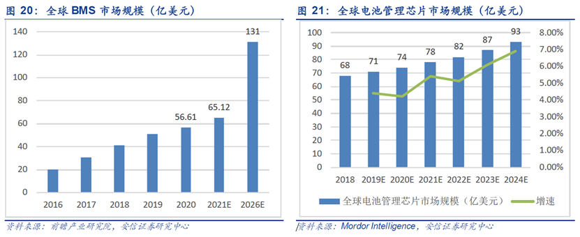
Among them, the rapid growth of the electric vehicle industry is driving the rapid development of BMS. According to statistics and analysis from the Forward Industry Research Institute, in 2020, among global BMS downstream applications: power battery applications accounted for 54%, consumer batteries accounted for 22%, and energy storage and other batteries accounted for 24%. According to estimates from Business Wire and compiled by the Forward Industry Research Institute, the global BMS market size is expected to reach $6.512 billion in 2021 and $13.1 billion by 2026, with a CAGR of 15%. According to Mordor Intelligence, the global battery management chip market is expected to reach $9.3 billion by 2024, indicating a vast market space.
The Battery Management Integrated Circuit (BMIC) is an important subdivision of power management chips, including charging management chips, battery measuring chips, and battery safety chips. Charging management chips can convert external power sources into suitable charging voltage and current for the cells, and monitor the charging status of the cells in real-time during the charging process, adjusting and controlling the charging voltage and current to ensure safe and efficient charging of the cells. Based on the characteristics of lithium batteries, charging management chips automatically perform pre-charge, constant current charging, and constant voltage charging, effectively controlling the charging state at each stage.
Charging management chips can be divided into switching mode, linear mode, and charge pump mode based on their working modes. Switching mode is highly efficient, suitable for high current applications, and can be flexibly designed as buck, boost, or buck-boost architectures. Common fast charging solutions are usually in switching mode. Linear mode is suitable for low-power portable electronic products, with lower requirements for charging current and efficiency, typically not exceeding 1A, but has higher requirements for size and cost. Charge pump mode can achieve efficiencies of over 97%, but due to architectural reasons, its output voltage is usually in a fixed ratio with the input voltage, and in practical applications, it is usually used in conjunction with switching-type charging management chips.
Charge pump charging management chips use a switched capacitor method for controlling the conversion of charging voltage and current. Compared to general charging management chips, charge pump chips do not require inductors, offering higher efficiency, higher power density, and lower heat generation, and have become one of the mainstream solutions for high-power charging above 22.5W for mobile phones.
In addition, with the popularity of wireless charging for mobile phones, wireless charging management chips have gradually become an important branch of charging management chip products. Wireless charging includes wireless transmitter chips and wireless receiver chips, widely used in wireless charging pads, wireless car chargers, wireless power banks, and mobile phones. The transmitter chip generally includes a Tx analog front end and a Tx embedded chip, supporting a 20W transmission power; the receiver chip is a TRx embedded chip, mainly used in mobile phone receivers, supporting a maximum receiving power of 50W.
The battery measurement chip (battery gauge IC) is mainly used to collect information such as cell voltage, temperature, and current, calculating battery capacity and health information through Coulomb counting and battery modeling, and communicating with external hosts via I2C/SMBUS/HDQ and other communication ports. The gauge IC can be discrete or integrated with battery protection ICs. The primary protection IC can control charge and discharge MOSFETs, with protection actions being recoverable, meaning that when overcharging, over-discharging, overcurrent, short-circuit, and other safety events occur, the corresponding charge and discharge switches will disconnect, and once the safety event is resolved, the switches will automatically reconnect, allowing the battery to continue to be used.
Hardware, algorithms, and firmware are the three core elements of the battery gauge chip. The hardware is used to achieve high-precision sampling and low-power operation; the algorithm is used for battery modeling; and the firmware is used to implement algorithm programming and calculate output capacity information. When selecting a battery gauge chip, it is usually necessary to consider the chemical type of the cell, the number of cells in series, the communication interface, whether the gauge is placed inside the battery pack (Pack-side) or on the system board (System-side), battery calculation methods, whether to integrate battery protection balancing functions, support for charge and discharge current sizes, as well as storage media and packaging forms.
Compared to System-side gauges, Pack-side gauge chips sample cell voltage directly, making the voltage more accurate, which is beneficial for improving measurement accuracy, charging, and protection; Pack-side gauges using integrated encryption authentication algorithms have lower overall costs; Pack-side battery protection boards PCM are easier to calibrate for voltage, current, and temperature, leading to shorter project development cycles; Pack-side gauges retain RAM data without loss when facing pluggable batteries, leading to more accurate data.
The battery gauge chip belongs to mixed-signal chips, involving measurement algorithms, AFE/ADC, and computation circuits, with core technologies reflected in measurement accuracy, managing the number of battery strings, platform voltage, and power consumption levels. The AFE comes with an ADC for analog-to-digital conversion, but requires an embedded microcontroller (MCU) to achieve gauge functionality.
The embedded processor is the core of embedded systems, serving as the hardware unit that controls and assists system operation. Embedded processors can be divided into embedded microprocessors (MPUs), embedded microcontrollers (MCUs), embedded DSP processors (EDSP), and embedded system-on-chip (SoC). Battery management chips are typically in the form of SoCs, directly embedding software code in the on-chip processor, seamlessly combining hardware and software to flexibly monitor, measure, control, and communicate battery status, consolidating many issues that previously needed system design solutions into chip design, thereby simplifying system design, increasing integration, reducing system power consumption, and improving reliability.
Main Application Markets for BMS
BMS chip solutions are typically built around battery management ICs, integrating low-power MCUs and high-performance analog front ends (AFEs) in a single package, and providing development tools to support the development of safe and reliable lithium battery management systems. The application range of BMS is very broad, from basic consumer applications such as mobile phones, laptops, electric tools, and electric motorcycles, to industrial applications such as communication base stations, electric vehicles, photovoltaic backup power supplies, and military equipment.
Among them, the rapid growth of the electric vehicle industry is driving the rapid development of BMS. According to statistics and analysis from the Forward Industry Research Institute, in 2020, among global BMS downstream applications: power battery applications accounted for 54%, consumer batteries accounted for 22%, and energy storage and other batteries accounted for 24%. According to estimates from Business Wire and compiled by the Forward Industry Research Institute, the global BMS market size is expected to reach $6.512 billion in 2021 and $13.1 billion by 2026, with a CAGR of 15%. According to Mordor Intelligence, the global battery management chip market is expected to reach $9.3 billion by 2024, indicating a vast market space.
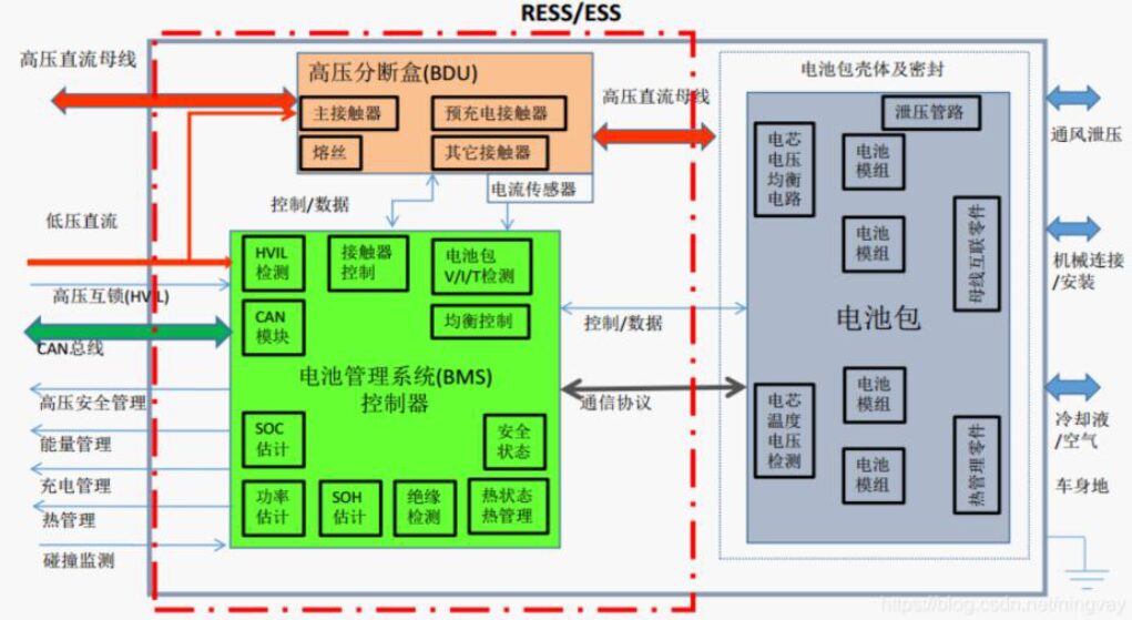
 The automotive power battery BMS is connected to the battery on one end and to the vehicle control and electronic systems on the other end, communicating in real-time with the onboard master controller, motor controller, energy control system, and vehicle display system via the CAN bus interface. Compared to consumer batteries and energy storage batteries, power batteries need to operate in high-temperature and vibration environments and are generally module batteries, which consist of multiple cells. They need to handle signals from cells, collisions, CAN, pumps, high voltage, insulation, etc., requiring higher reliability and stability.
Common system architecture of automotive BMS. (Source: CSDN, Anxin Securities Research Center)
Automotive BMS involves multiple core technologies, primarily including battery temperature and voltage/current collection, SOX estimation, charging control, thermal management, relay diagnostics, high-voltage safety, and fault diagnosis. Battery temperature and voltage are key parameters of the battery, and BMS control is based on analyzing and controlling these parameters. The temperature collected by temperature sensors determines whether the battery is in an over-temperature state. High voltage boxes can be used to collect total battery voltage, while Hall current sensors or shunts can be used to collect current. SOX estimation refers to battery state estimation, including SOC, SOH, and SOP estimates, which is the core technology of BMS. According to statistics from the Automotive Research Institute, the accuracy level of some leading BMS companies can reach as high as 3%, while first-line BMS manufacturers in China reach about 5%, and second-line manufacturers range from 5% to 10%.
The system structure of BMS is divided into centralized, distributed, and semi-centralized structures. Due to the high replicability of distributed management architectures, they can be applied to various vehicle battery packs, which is expected to support the sustainable development of new energy vehicles. In addition, BMS balancing modes are divided into active balancing (energy transfer balancing) and passive balancing (energy dissipation balancing). Passive balancing management is widely used by domestic and foreign companies due to its low cost, low complexity, and low failure rate, while active balancing management is more efficient, with larger balancing currents and less energy dissipation. As thermal risks and circuit complexity are gradually overcome, BMS is expected to transition to active balancing management. Therefore, distributed management architecture and active balancing management will be the future technological trends for automotive BMS.
Furthermore, with technological advancements and the development of the BMS market, two solutions have gradually emerged: wired BMS and wireless BMS. In wired BMS solutions, twisted pair cables are typically used to connect battery monitors in a daisy chain to transmit data collected from each battery module; while wireless BMS solutions use wireless communication interfaces to transmit this data.
In 2019, ADI acquired Linear Technology and collaborated with automakers such as General Motors to develop wireless BMS, launching wireless BMS systems and platforms that detect and analyze battery data throughout the entire life cycle from production to recycling, maximizing the value of power batteries. In 2021, TI announced the launch of a wireless BMS solution certified for functional safety by TÜV SÜD, achieving wireless transmission of battery data and control commands. Its SimpleLink CC2662R-Q1 wireless MCU meets AEC-Q100 standards, is based on Arm Cortex-M4, integrates rich analog peripherals and a radio frequency subsystem, and includes a dedicated wireless BMS protocol stack, operating in the 2.4GHz band and incorporating TI-RTOS to support rapid networking.
The battery management module in automotive BMS mainly includes hardware circuits such as active balancing, AFE, MCU, isolation circuits, etc. The AFE is an integrated component that includes sensor interfaces, analog signal conditioning (including impedance transformation, programmable gain amplification, filtering, and polarity conversion), analog multiplexers, sample and hold circuits, ADCs, data buffers, and control logic. Some AFEs also come with MCUs, DACs, and various driver circuits.
Battery imbalance affects battery endurance and cycle life. Balancing circuits mainly include active balancing and passive balancing. Active balancing transfers the excess charge from the cell with the most charge to the cell with the least charge, or to the entire string of batteries, achieving energy recovery. Passive balancing dissipates excess charge from the cell with the most charge through resistors.
The MCU, as the computing platform, needs to meet AEC-Q100, ISO26262, and other certifications. Taking ADI’s 48V hybrid BMS system as an example, the MCU plays roles in relay control, SOC/SOH estimation, balancing control, collecting data on cell voltage, current, and temperature, and data storage. Compared to consumer-grade and industrial-grade MCUs, automotive-grade MCUs have higher industry barriers.
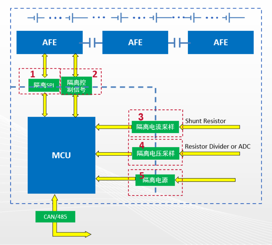
Isolation devices achieve electrical isolation between high-voltage and low-voltage modules, including opto-isolation and digital isolation. Electrical isolation ensures the safety of signal transmission between high-power circuits and low-power circuits; without electrical isolation, in the event of a fault, high-power circuit current could directly flow into low-power circuits, damaging the circuits and devices.
Diagram of high-voltage energy storage BMS isolation products from Naxin Micro. (Source: Naxin Micro)
As the four transformations of the automotive industry continue to develop, the BMS in power batteries is no longer just a simple charging and discharging protection function, but gradually provides management functions such as stable pulse discharge and multi-cell balancing management, transitioning from “protective BMS” to “intelligent BMS”.
Anxin Securities Research Center: Accelerating the Domestic Substitution Process of Battery Management BMS/BMIC Chips
Wikipedia: https://en.wikipedia.org/wiki/Battery_management_system
Synopsys: What is a Battery Management System?
The automotive power battery BMS is connected to the battery on one end and to the vehicle control and electronic systems on the other end, communicating in real-time with the onboard master controller, motor controller, energy control system, and vehicle display system via the CAN bus interface. Compared to consumer batteries and energy storage batteries, power batteries need to operate in high-temperature and vibration environments and are generally module batteries, which consist of multiple cells. They need to handle signals from cells, collisions, CAN, pumps, high voltage, insulation, etc., requiring higher reliability and stability.
Common system architecture of automotive BMS. (Source: CSDN, Anxin Securities Research Center)
Automotive BMS involves multiple core technologies, primarily including battery temperature and voltage/current collection, SOX estimation, charging control, thermal management, relay diagnostics, high-voltage safety, and fault diagnosis. Battery temperature and voltage are key parameters of the battery, and BMS control is based on analyzing and controlling these parameters. The temperature collected by temperature sensors determines whether the battery is in an over-temperature state. High voltage boxes can be used to collect total battery voltage, while Hall current sensors or shunts can be used to collect current. SOX estimation refers to battery state estimation, including SOC, SOH, and SOP estimates, which is the core technology of BMS. According to statistics from the Automotive Research Institute, the accuracy level of some leading BMS companies can reach as high as 3%, while first-line BMS manufacturers in China reach about 5%, and second-line manufacturers range from 5% to 10%.
The system structure of BMS is divided into centralized, distributed, and semi-centralized structures. Due to the high replicability of distributed management architectures, they can be applied to various vehicle battery packs, which is expected to support the sustainable development of new energy vehicles. In addition, BMS balancing modes are divided into active balancing (energy transfer balancing) and passive balancing (energy dissipation balancing). Passive balancing management is widely used by domestic and foreign companies due to its low cost, low complexity, and low failure rate, while active balancing management is more efficient, with larger balancing currents and less energy dissipation. As thermal risks and circuit complexity are gradually overcome, BMS is expected to transition to active balancing management. Therefore, distributed management architecture and active balancing management will be the future technological trends for automotive BMS.
Furthermore, with technological advancements and the development of the BMS market, two solutions have gradually emerged: wired BMS and wireless BMS. In wired BMS solutions, twisted pair cables are typically used to connect battery monitors in a daisy chain to transmit data collected from each battery module; while wireless BMS solutions use wireless communication interfaces to transmit this data.
In 2019, ADI acquired Linear Technology and collaborated with automakers such as General Motors to develop wireless BMS, launching wireless BMS systems and platforms that detect and analyze battery data throughout the entire life cycle from production to recycling, maximizing the value of power batteries. In 2021, TI announced the launch of a wireless BMS solution certified for functional safety by TÜV SÜD, achieving wireless transmission of battery data and control commands. Its SimpleLink CC2662R-Q1 wireless MCU meets AEC-Q100 standards, is based on Arm Cortex-M4, integrates rich analog peripherals and a radio frequency subsystem, and includes a dedicated wireless BMS protocol stack, operating in the 2.4GHz band and incorporating TI-RTOS to support rapid networking.
The battery management module in automotive BMS mainly includes hardware circuits such as active balancing, AFE, MCU, isolation circuits, etc. The AFE is an integrated component that includes sensor interfaces, analog signal conditioning (including impedance transformation, programmable gain amplification, filtering, and polarity conversion), analog multiplexers, sample and hold circuits, ADCs, data buffers, and control logic. Some AFEs also come with MCUs, DACs, and various driver circuits.
Battery imbalance affects battery endurance and cycle life. Balancing circuits mainly include active balancing and passive balancing. Active balancing transfers the excess charge from the cell with the most charge to the cell with the least charge, or to the entire string of batteries, achieving energy recovery. Passive balancing dissipates excess charge from the cell with the most charge through resistors.
The MCU, as the computing platform, needs to meet AEC-Q100, ISO26262, and other certifications. Taking ADI’s 48V hybrid BMS system as an example, the MCU plays roles in relay control, SOC/SOH estimation, balancing control, collecting data on cell voltage, current, and temperature, and data storage. Compared to consumer-grade and industrial-grade MCUs, automotive-grade MCUs have higher industry barriers.
Isolation devices achieve electrical isolation between high-voltage and low-voltage modules, including opto-isolation and digital isolation. Electrical isolation ensures the safety of signal transmission between high-power circuits and low-power circuits; without electrical isolation, in the event of a fault, high-power circuit current could directly flow into low-power circuits, damaging the circuits and devices.
Diagram of high-voltage energy storage BMS isolation products from Naxin Micro. (Source: Naxin Micro)
As the four transformations of the automotive industry continue to develop, the BMS in power batteries is no longer just a simple charging and discharging protection function, but gradually provides management functions such as stable pulse discharge and multi-cell balancing management, transitioning from “protective BMS” to “intelligent BMS”.
Anxin Securities Research Center: Accelerating the Domestic Substitution Process of Battery Management BMS/BMIC Chips
Wikipedia: https://en.wikipedia.org/wiki/Battery_management_system
Synopsys: What is a Battery Management System?