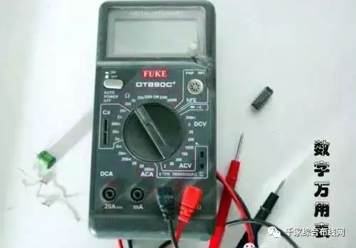
A multimeter is a multifunctional and multirange measuring instrument that is indispensable in electronic and electrical technology. Generally, a multimeter can measure direct current, direct voltage, alternating current, alternating voltage, resistance, and audio level, among others. Some can also measure capacitance, inductance, and certain parameters of semiconductors (such as β). Based on the display method, multimeters can be categorized into analog multimeters and digital multimeters.
Comparison of Analog and Digital Multimeters
Both analog and digital multimeters have their pros and cons, and below is a comparative analysis.
Analog multimeters are average value type instruments, providing intuitive and visual reading indications. (The reading value is closely related to the angle of the pointer’s swing, making it very intuitive).
Digital multimeters are instantaneous sampling type instruments. They take a sample every 0.3 seconds to display the measurement result, and sometimes the results of each sample are only very close but not exactly the same, making it less convenient than analog meters for reading results.
Analog multimeters generally have no amplifiers inside, hence they have lower internal resistance.
Digital multimeters, due to the use of operational amplifier circuits internally, can have very high internal resistance, often at 1M ohm or more (thus achieving higher sensitivity). This minimizes the impact on the measured circuit, resulting in higher measurement accuracy.
Due to their lower internal resistance, analog multimeters often use discrete components to construct shunt and voltage divider circuits, leading to uneven frequency characteristics (relative to digital types), while analog multimeters have relatively better frequency characteristics.
Analog multimeters are simpler in internal structure, thus lower in cost, with fewer functions, easy maintenance, and strong overload capability. Digital multimeters incorporate various oscillation, amplification, frequency division protection circuits, and thus have more functions. For example, they can measure temperature, frequency (within a lower range), capacitance, inductance, and act as signal generators, etc.
Digital multimeters generally have poorer overload capability due to their complex internal structure (though some can now automatically switch ranges and provide automatic protection, but they are more complex to use), and they are generally difficult to repair once damaged.
Digital multimeters output a lower voltage (usually not exceeding 1 volt), making it inconvenient to test components with special voltage characteristics (such as thyristors, light-emitting diodes, etc.).
Analog multimeters output a higher voltage (e.g., 10.5 volts, 12 volts, etc.) and also have a larger current (e.g., the MF-500 1-ohm range can measure up to about 100 milliamps), making it convenient to test thyristors, light-emitting diodes, etc.
Choosing Between Analog and Digital Meters
1. Analog meters have poorer reading accuracy, but the process of the pointer’s swing is more intuitive, and its swing speed and amplitude can sometimes objectively reflect the size of the measurement (for instance, slight jitter when measuring the data bus (SDL) of a television during data transmission); digital meters provide intuitive readings, but the changing digits can appear chaotic and are less easy to observe.
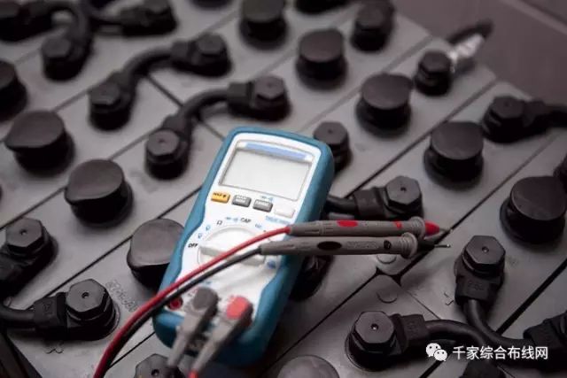
2. Analog meters typically contain two batteries, one low voltage 1.5V and one high voltage 9V or 15V, with the black probe being the positive terminal relative to the red probe. Digital meters commonly use a 6V or 9V battery. In resistance mode, the output current of the analog meter’s probes is significantly larger than that of the digital meter; using the R×1Ω range can make a speaker emit a loud “click” sound, and using the R×10kΩ range can even light up a light-emitting diode (LED).
3. In voltage mode, the internal resistance of the analog meter is relatively lower than that of the digital meter, leading to poorer measurement accuracy. In certain high-voltage microcurrent scenarios, it may even be unable to measure accurately, as its internal resistance can affect the measured circuit (for instance, when measuring the accelerating voltage of a television’s cathode ray tube, the measured value can be significantly lower than the actual value). The internal resistance of the digital meter in voltage mode is very high, at least in the megaohm range, which minimally affects the measured circuit. However, the extremely high output impedance makes it susceptible to induced voltages, and in scenarios with strong electromagnetic interference, the data obtained may be false.
4. In summary, analog meters are suitable for measuring analog circuits with relatively high current and high voltage, such as televisions and audio amplifiers. Digital meters are suitable for measuring digital circuits with low voltage and small current, such as pagers and mobile phones. This is not absolute, and the choice between analog and digital meters can depend on the situation.
Functions of a Multimeter
The three basic functions of a multimeter are measuring resistance, voltage, and current, which is why it was historically referred to as a three-use meter. Modern multimeters have added many new functions, especially digital multimeters, such as measuring capacitance, transistor gain, diode voltage drop, etc., and there are even talking digital multimeters that can announce measurement results vocally.
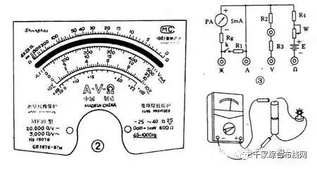
The most notable feature of a multimeter is the range switch, which is used to switch between various functions. Generally, A- is used to indicate measuring direct current, with milliamp and amp ranges further divided. V- indicates measuring direct voltage, and higher-end multimeters have a millivolt range, with voltage ranges also divided. V~ is used to measure alternating voltage. A~ measures alternating current. The Ω ohm range measures resistance; for analog multimeters, each time the resistance range is changed, a zero adjustment is required. Zero adjustment involves connecting the red and black probes of the multimeter together and turning the zero adjustment knob to make the pointer point to zero. hFE is used to measure the current gain of transistors; simply insert the three pins of the transistor into the corresponding holes on the multimeter’s panel to measure the hFE value. Note that PNP and NPN are different.
Instructions for Using a Multimeter
Taking the MF30 multimeter as an example, the first scale line indicates resistance values, with the leftmost end indicating infinity and the right end indicating zero, with uneven scales in between. The resistance ranges include R×1, R×10, R×100, R×1K, R×10K, each indicating the multiplication factor to obtain the actual resistance value (in ohms).
For example, measuring a resistor with the R×100 range, if the pointer indicates “10”, then its resistance value is 10×100=1000, or 1K. The second scale line is shared by the 500V and 500mA ranges, and it is important to note that the indication principles for voltage and current ranges differ from those for resistance ranges; for example, the 5V range indicates that this range can only measure voltages below 5V, and the 500mA range can only measure currents below 500mA. Exceeding the range may damage the multimeter.
Precautions: The multimeter should be placed horizontally during use. The red probe should be inserted into the + socket, and the black probe should be inserted into the – socket. Use the current range for testing current, and do not mistakenly use the voltage or resistance ranges; otherwise, it may burn the multimeter’s fuse or, in severe cases, damage the meter head. If the range is unknown, select the maximum range to attempt measurement, then disconnect the measurement circuit before changing the range; do not switch ranges while connected. If the pointer quickly deflects to the end, immediately disconnect the circuit and check.
Finally, there is a rule: after use, the multimeter’s range switch should be set to the highest AC voltage range to prevent someone from accidentally measuring the 220V mains voltage and causing damage. Remember this good tradition left by our predecessors!
Usage Examples
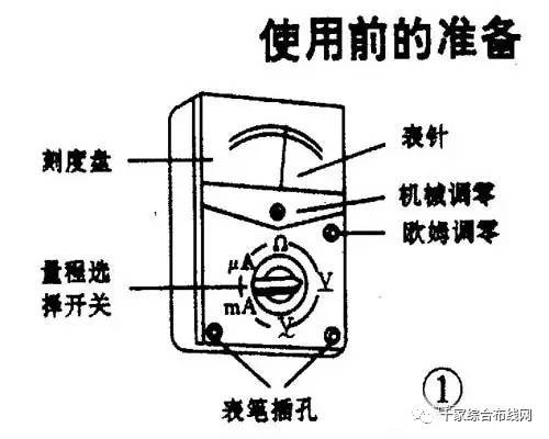
Taking the MF30 multimeter as an example, here are the instructions for its use. Preparations before use:
First, before using the multimeter, you must familiarize yourself with the function of the range selector switch. Clarify what you want to measure and how to measure it, then set the range selector switch to the required test range. Do not make mistakes with the range settings. For example, when measuring voltage, do not mistakenly set the selector switch to current or resistance ranges, as this can easily damage the meter head.
Second, check if the pointer is at zero before use. If it is not at zero, use a screwdriver to adjust the zeroing screw on the meter head to bring the pointer back to zero (generally, this does not need to be adjusted every time). The red probe should be plugged into the positive terminal, and the black probe should be plugged into the negative terminal.
For voltage measurement, align the pointer of the range selector switch with the marked V on the five-range scale. If measuring AC voltage, it should point to V~. Similarly, if you want to measure resistance, the switch should point to the resistance range. For measuring current, it should point to mA or μA. For example, to measure the voltage of a dry battery, see Figure 4.
When measuring voltage, connect the meter probes across the circuit being measured. Based on the approximate value of the measured circuit, select an appropriate range position. A dry battery has a maximum value of 1.5V, so you can set it to the 5V range. At this time, the full-scale reading of 500 on the panel should be read as 5, meaning it is scaled down by 100 times. If the pointer indicates 300, the reading would be 3V. Note that the value indicated by the range switch pointer corresponds to the full-scale reading on the meter head, and when reading the meter, just calculate based on this to get the actual value. All ranges except the resistance range are read this way. In actual measurement, if you cannot determine the approximate value of the measured voltage, you can first set the switch to the maximum range and then gradually reduce the range to an appropriate position. When measuring DC voltage, pay attention to the polarity; if the probes are reversed, the pointer will deflect in the opposite direction. If the polarity of the circuit is unknown, set the multimeter to the maximum range and quickly test the circuit to see how the pointer deflects to determine the polarity.
Example 2, measuring 220V AC. Set the range switch to the AC 500V range. The full-scale value is 500V, and the reading is taken according to a 1:1 scale. Insert the two probes into the power outlet, and the scale indicated by the pointer is the measured voltage value. There is no positive or negative distinction when measuring AC voltage.
Mnemonics for Using a Multimeter
1. Check the range before measuring; do not measure without checking.
Whenever you pick up the probes to prepare for measurement, be sure to double-check the measurement category and the position of the range selector switch for safety.
2. Do not change the range during measurement; switch to the empty range after measuring.
During measurement, do not arbitrarily turn the selection knob, especially when measuring high voltage (like 220V) or high current (like 0.5A), to avoid generating arcs that may damage the contacts of the switch. After measurement, set the range selector switch to the “?” position.
3. The dial should be level, and the reading should be aligned.
When using a multimeter, it should be held horizontally, and the line of sight should be directly aligned with the pointer when reading.
4. The range should be appropriate; the pointer should deflect more than half.
When choosing the range, if you cannot estimate the size of the measured value in advance, try to select a larger range first, then gradually switch to a smaller range based on the size of the pointer’s deflection until it deflects about 2/3 of the full scale.
5. Do not measure resistance while powered; discharge capacitors before measuring capacitance.
It is strictly forbidden to measure resistance in a powered circuit. When checking large capacitors in electrical equipment, discharge the capacitor before measuring.
6. Zero adjustment is required before measuring resistance; zero adjustment is needed when changing ranges.
When measuring resistance, first turn the switch to the resistance range, short-circuit the two probes, and turn the “Ω” zero adjustment potentiometer to make the pointer point to zero ohms before measuring. Every time the resistance range is changed, the zero point must be adjusted.
7. Remember the negative connection; the black probe is connected to the positive in the meter.
The red probe is positive, and the black probe is negative, but in the resistance range, the black probe connects to the positive terminal of the internal battery.
8. Connect in series to measure current; connect in parallel to measure voltage.
When measuring current, the multimeter should be connected in series with the circuit being measured; when measuring voltage, it should be connected in parallel across the two ends of the circuit being measured.
9. Do not reverse the polarity; develop a habit of using one hand.
When measuring current and voltage, pay particular attention to ensure that the red and black probes are not reversed, and always develop a habit of using one hand for safety.
END | Source: Qianjia Comprehensive Wiring Network
 Long press the QR code to recognize and pre-register


Long press the QR code to follow

Panyu District Employment Training Center | Public Training and Certification Base for High-Skilled Talents
Address: 8 Wanfeng Road, Shiqiao Street, Panyu District; 37 Shixin Road, Donghuan Street. Phone: 84825537, 84833634. Website: www.pyhome.com. Panyu Employment Training Network: www.panyuvtc.com
WeChat ID: PYJYXL