Digital measuring instruments have become mainstream due to their high sensitivity, accuracy, clear display, strong overload capacity, portability, and ease of use. The digital multimeter is relatively simple as a measuring instrument. Today, I will teach you the correct usage of a digital multimeter. We will start with measurement methods for voltage, resistance, current, diodes, and transistors, which are common settings we need to use during the electrical certification exam, allowing you to better master the multimeter measurement methods to help you successfully pass the exam.
1. Voltage Measurement
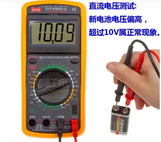
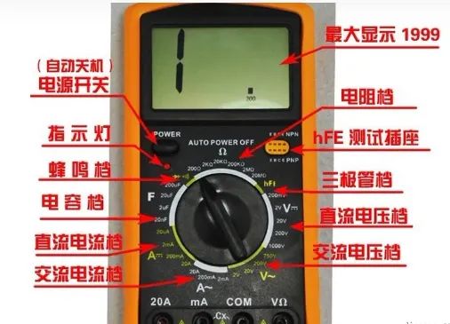
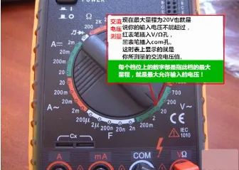
1. Measuring DC voltage, such as batteries or portable audio player power supplies. First, insert the black probe into the “com” hole and the red probe into the “V Ω” hole. Set the knob to a range larger than the estimated value (Note: the values on the dial are the maximum ranges. “V-” indicates the DC voltage range, “V~” indicates the AC voltage range, and “A” is for current measurement). Then connect the probes to both ends of the power supply or battery; maintain stable contact. The value can be read directly from the display. If it shows “1.”, it indicates that the range is too small, so you need to increase the range before measuring industrial electrical devices. If a “-” appears on the left side of the value, it indicates that the probe polarity is opposite to the actual power polarity, meaning the red probe is connected to the negative terminal.
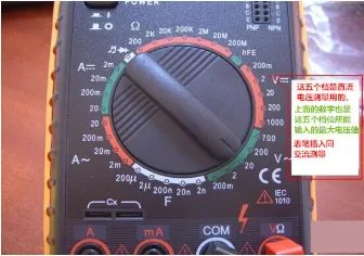
2. Measuring AC voltage. The probe connections are the same as for DC voltage measurement, but the knob should be turned to the AC range “V~”. There is no positive or negative for AC voltage, and the measuring method is the same as before. Whether measuring AC or DC voltage, always pay attention to personal safety and avoid touching the metal parts of the probes with your hands.
2. Current Measurement
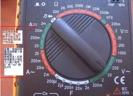
1. Measuring DC current. First, insert the black probe into the “COM” hole. If measuring current greater than 200mA, insert the red probe into the “10A” hole and set the knob to the DC “10A” range; if measuring current less than 200mA, insert the red probe into the “200mA” hole and set the knob to an appropriate range under 200mA. After setting up, you can measure. Insert the multimeter in series with the circuit and maintain stability to read the value. If it shows “1.”, you need to increase the range; if a “-” appears on the left side of the value, it indicates that the current is flowing from the black probe into the multimeter.
3. Resistance Measurement
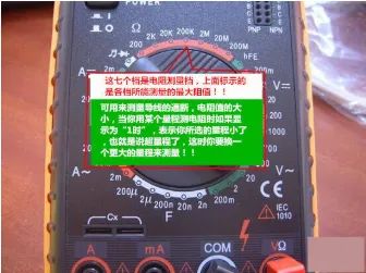
Insert the probes into the “COM” and “VΩ” holes, turn the knob to the desired resistance range “Ω”, and connect the probes to the metal parts on both ends of the resistor. During measurement, you can touch the resistor with your hands, but do not touch both ends at the same time, as this will affect measurement accuracy— the human body is a large but limited conductor of resistance. When reading, ensure good contact between the probes and the resistor; pay attention to the units: in the “200” range the unit is “Ω”, in the “2K” to “200K” range the unit is “KΩ”, and above “2M” the unit is “MΩ”.
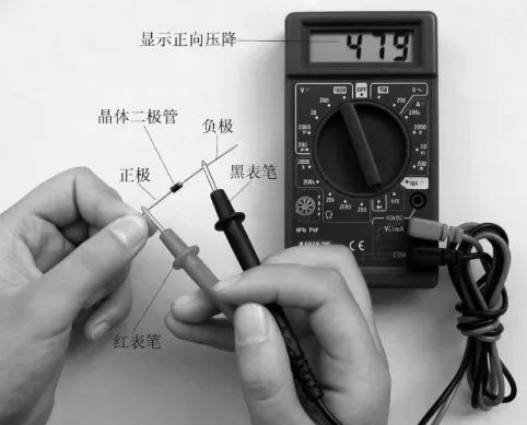
4. Diode Measurement
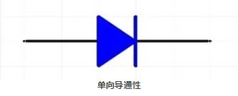
The digital multimeter can measure light-emitting diodes and rectifier diodes… For measurement, the probe positions are the same as for voltage measurement; turn the knob to the diode range; connect the red probe to the positive terminal of the diode and the black probe to the negative terminal. This will display the forward voltage drop of the diode. The forward voltage drop for Schottky diodes is around 0.2V, for regular silicon rectifiers (1N4000, 1N5400 series, etc.) it is about 0.7V, and for light-emitting diodes it is about 1.8~2.3V. If you swap the probes and the display shows “1.”, this is normal because the reverse resistance of the diode is very high; otherwise, the diode has been broken down.
Summary: Notes on Using Digital Multimeters
1. If you cannot estimate the size of the voltage or current to be measured in advance, you should first set it to the highest range to measure once,
then gradually reduce the range to an appropriate position depending on the situation. After measurement, set the range switch back to the highest voltage range and turn off the power.
2. When at full scale, the instrument will only display the digit “1” at the highest position, and other positions will disappear; at this time, you should select a higher range.
3. When measuring voltage, the digital multimeter should be connected in parallel with the circuit being measured. When measuring current, it should be connected in series with the circuit being measured, and when measuring DC, there is no need to consider positive and negative polarity.
4. If you mistakenly use the AC voltage range to measure DC voltage, or mistakenly use the DC voltage range to measure AC voltage, the display will show “000”, or the digits on the lower position will fluctuate.
5. It is prohibited to change the range while measuring high voltage (above 220V) or large current (above 0.5A) to prevent arcing and burning the switch contacts.