

Click the blue words to follow us
The Siemens PLC is a major player in the field of industrial automation, but those new to it may find it complex and difficult to understand. Don’t worry, today we will unveil the mystery of Siemens PLC and learn how to design an efficient automation solution with it!
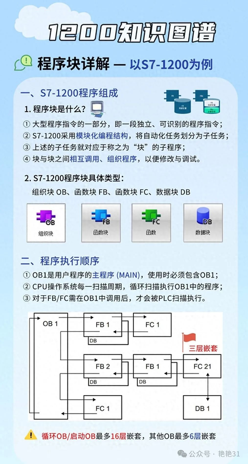
We need to understand the basic components of Siemens PLC. A typical PLC system includes:
-
CPU Unit: Equivalent to the PLC’s “brain”, responsible for executing programs and processing data. -
Input/Output Modules: Like the PLC’s “hands and feet”, used to receive external signals and control devices. -
Communication Module: The PLC’s “mouth”, used for exchanging data with other devices. -
Power Supply Module: Provides energy for the entire system.
These modules combine like building blocks to form a complete PLC system.
Selecting the right PLC model is the first step in designing a solution. Siemens offers several series of PLCs, such as the S7-1200 which is suitable for small to medium applications, while the S7-1500 is more suited for large and complex systems. When selecting, consider factors like control points, processing speed, and communication needs. It’s like buying a computer; you should choose the configuration based on your usage requirements.
Next is hardware configuration. This step is like “assembling the body” of the PLC. In the TIA Portal software, we can intuitively drag and drop modules and set parameters. For example, configure the measurement range and resolution for an analog input module. Note: The slot positions of the modules must match the actual installation positions, otherwise the system may not function properly.
Once the hardware is configured, it’s time to write the program. Siemens PLC supports multiple programming languages, with the most common being Ladder Diagram (LAD) and Structured Control Language (SCL). For beginners, it’s recommended to start with Ladder Diagram as its graphical interface is more intuitive.
Let’s look at a simple example: suppose we want to control a conveyor belt that starts when an object passes a sensor and stops after 10 seconds. This can be implemented in Ladder Diagram as follows:
|--[ ]--|   |---(  )---|
Sensor     Motor_On
|--[/]--|   |--[TON]--|   |---(/)---|
Motor_On    T1           Motor_On
PT=10s
The logic of this program is as follows:
-
When the sensor detects an object, the Motor_On coil is energized, starting the motor. -
The Motor_On contact closes, activating timer T1. -
After 10 seconds, T1’s output contact closes, de-energizing the Motor_On coil and stopping the motor.
Programming Tip: Make good use of comments! Add clear comments to each network and important variables, as this will save a lot of trouble during future maintenance or handover work.
Once the program is written, it’s time for the debugging phase. TIA Portal provides powerful online monitoring features that allow real-time viewing of variable values and forced input/output. When encountering issues, you can set breakpoints and step through the program, which is like equipping the PLC with a “microscope” that helps us quickly locate faults.
Debugging Precautions: Be very cautious when running the program for the first time! It is best to test in a simulation environment first, and only run on actual devices after confirming everything is correct. There have been cases where engineers caused equipment malfunctions due to carelessness, resulting in losses.
Speaking of practical applications, the Siemens PLC has a wide range of uses. For example:
-
Production Line Automation: Controlling the coordinated operation of various machines. -
Building Automation: Managing systems like lighting, air conditioning, and elevators. -
Energy Management: Monitoring and optimizing energy usage.
In these applications, the PLC often needs to work in conjunction with other systems. For instance, it can work with frequency converters for precise motor speed control or combine with HMI (Human-Machine Interface) to facilitate operators in monitoring and controlling the system.
Optimization Tips: Reasonable use of interrupts and subroutines can greatly improve PLC execution efficiency. For example, place tasks that require rapid response in interrupt programs and encapsulate commonly used functions into subroutines for repeated calls.
Here are some practical design tips:
-
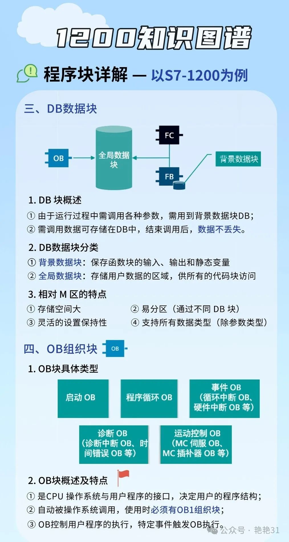
Modular Design: Break large systems into multiple functional modules, each implemented with a Function Block (FB). This not only facilitates management but also enhances code reusability.
-
Data Structuring: Use user-defined data types (UDT) to organize related data. For instance, you can define a “Motor” UDT that contains information such as speed, direction, and status.
-
Safety Design: Incorporate emergency stops, safety interlocks, and other functions. Safety should always be the top priority!
-
Reliability Design: Consider various abnormal situations, such as sensor failures and communication interruptions, ensuring that the system operates safely and reliably under all conditions.
-
User-Friendly Design: Design intuitive user interfaces and provide detailed alarm information for ease of operation and maintenance.
Practice makes perfect; it’s recommended to start with simple projects and gradually increase the difficulty. For example, you can first try controlling a simple traffic light with a PLC before challenging yourself with more complex production line control systems.
Remember, there are no shortcuts on the road to becoming a PLC master; continuous learning and practice are essential. But as long as you persevere, I believe you can also become an expert in the field of automation!
Reposting is a kind of motivation; sharing is a virtue.

Tap the button to give us a look before you leave!
