

[Disassembly] The Spectrum Light from My Memory
Author: Maruko~, Source: Breadboard Community [Write Disassembly, Win Drone Event]
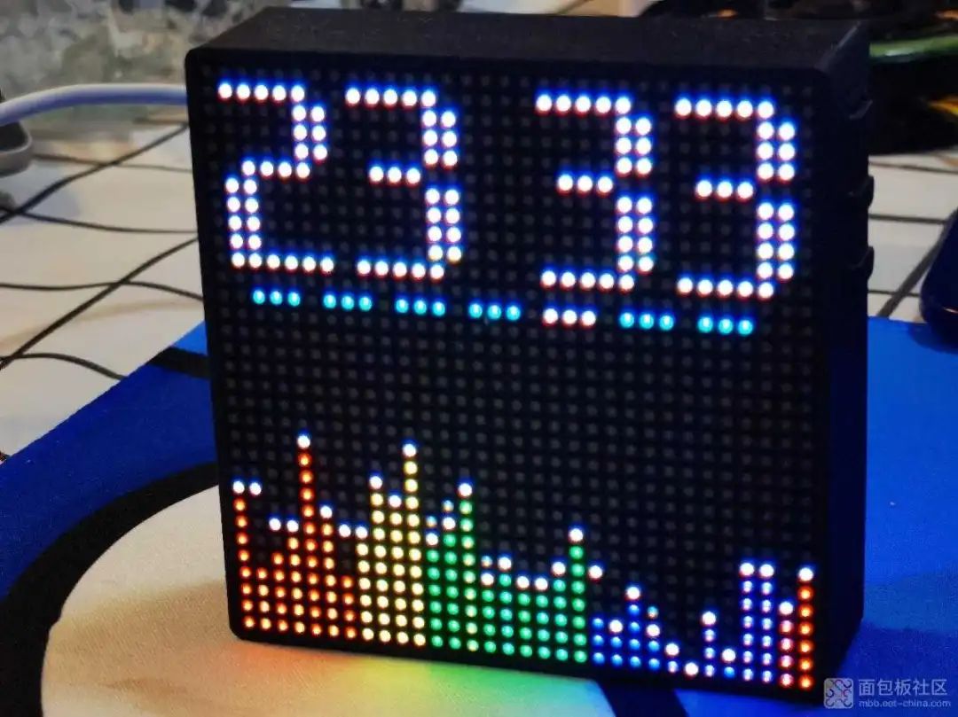
I remember being interested in electronics in high school because of the twinkling little lights. After entering university, every microcontroller student’s first step is to light up an LED, just like the first line of code is always a hello world greeting to the world. It was during that time that I came across some fun things, RGB dot matrix, FFT algorithms, and then discovered the spectrum light. The spectrum light looks very cool; it can pulse with the rhythm of music or your voice, and each line on the screen represents a frequency’s information. Most people should like such sparkling things. This thing is simple yet complex; the quality of the FFT algorithm and the refresh rate test the creator’s programming skills and hardware application level. I have made spectrum lights myself and purchased some, and the one I feel is the best is the one I am about to disassemble below. This spectrum light has a square design, with sides measuring ten centimeters and a thickness of two to three centimeters. The front screen can display large time digits, and the spectrum light is located below the screen.
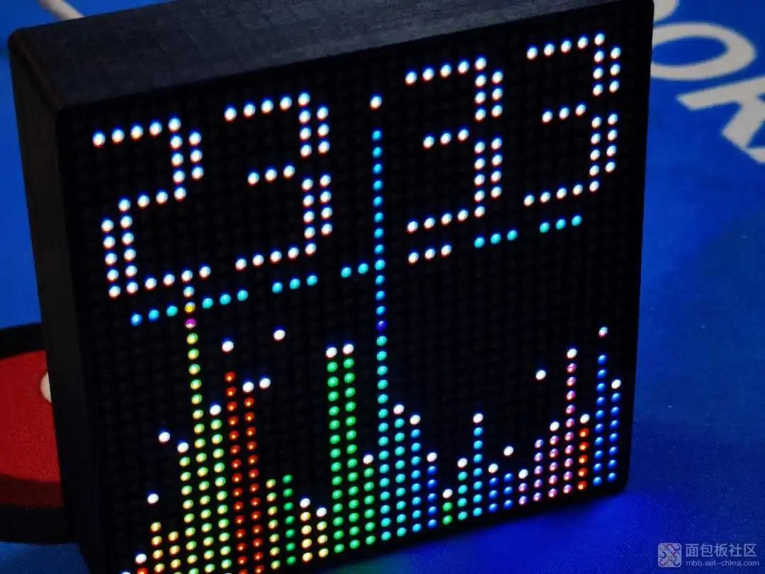
I have used many physical spectrum lights, and this one gives the best intuitive feeling, especially in terms of refresh rate. The term refresh rate may not be appropriate, but it is the easiest for everyone to understand; it is like a 120Hz high refresh screen, where every syllable’s rhythm can be captured.

Let’s take a closer look at the screen, which uses a dot matrix format. In the previous spectrum lights I made, the vast majority used WS2812 single-wire LED beads, where one wire controls the entire screen.
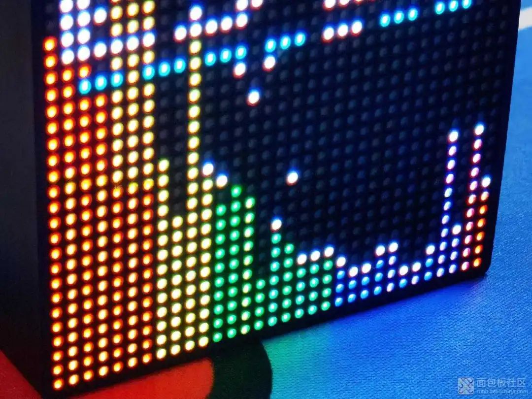
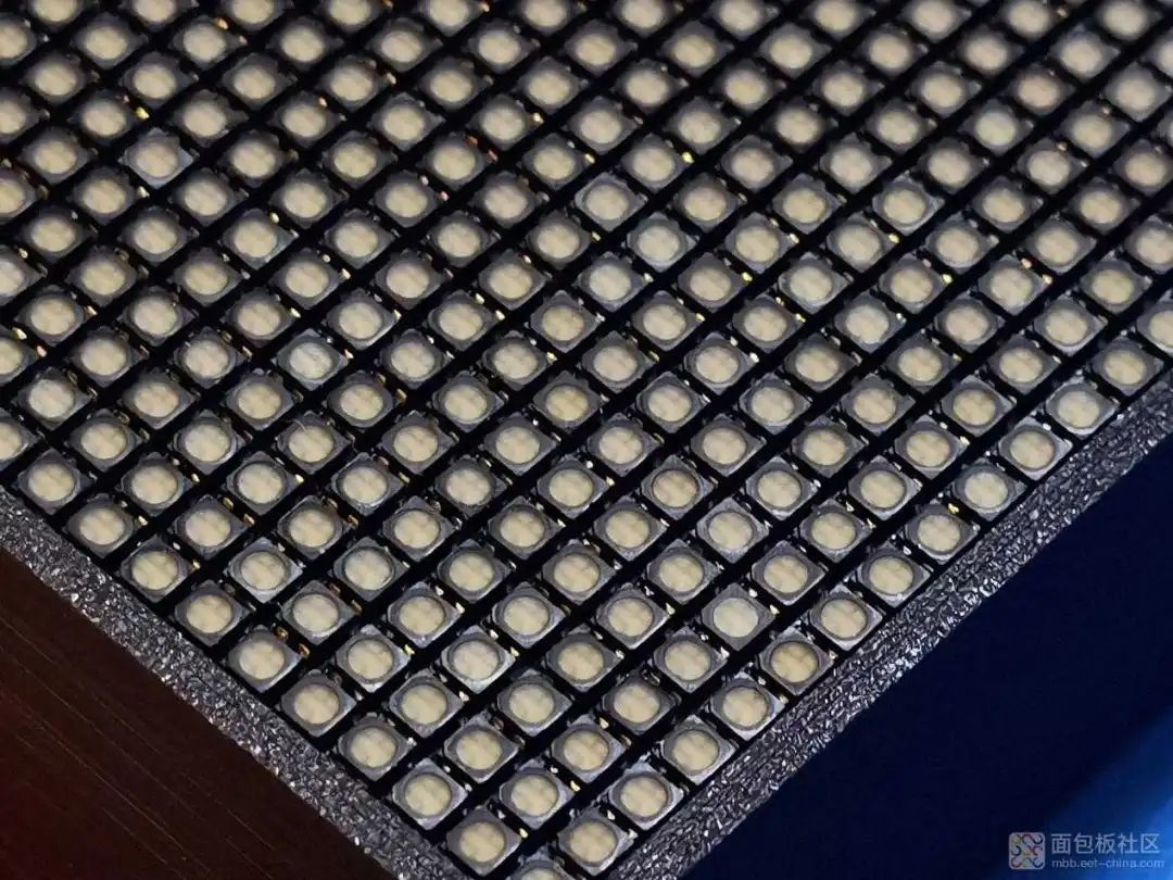
Here you can see the densely packed LED beads.
It can be seen that ordinary RGB beads are used here, which means there must be a separate driver chip, and the architecture is almost the same as that of outdoor advertising large screens.
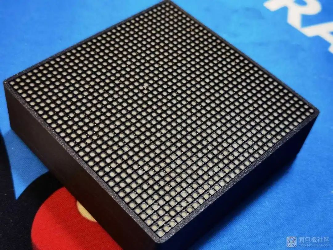
Its back panel is made of transparent acrylic, let’s call it the “true transparent exploration version”, with heat dissipation holes above the easily heated main control.

The side has three buttons, and the shell is 3D printed, so it feels a bit rough. The transparent cover is fixed to the plastic pillar with soft screws.
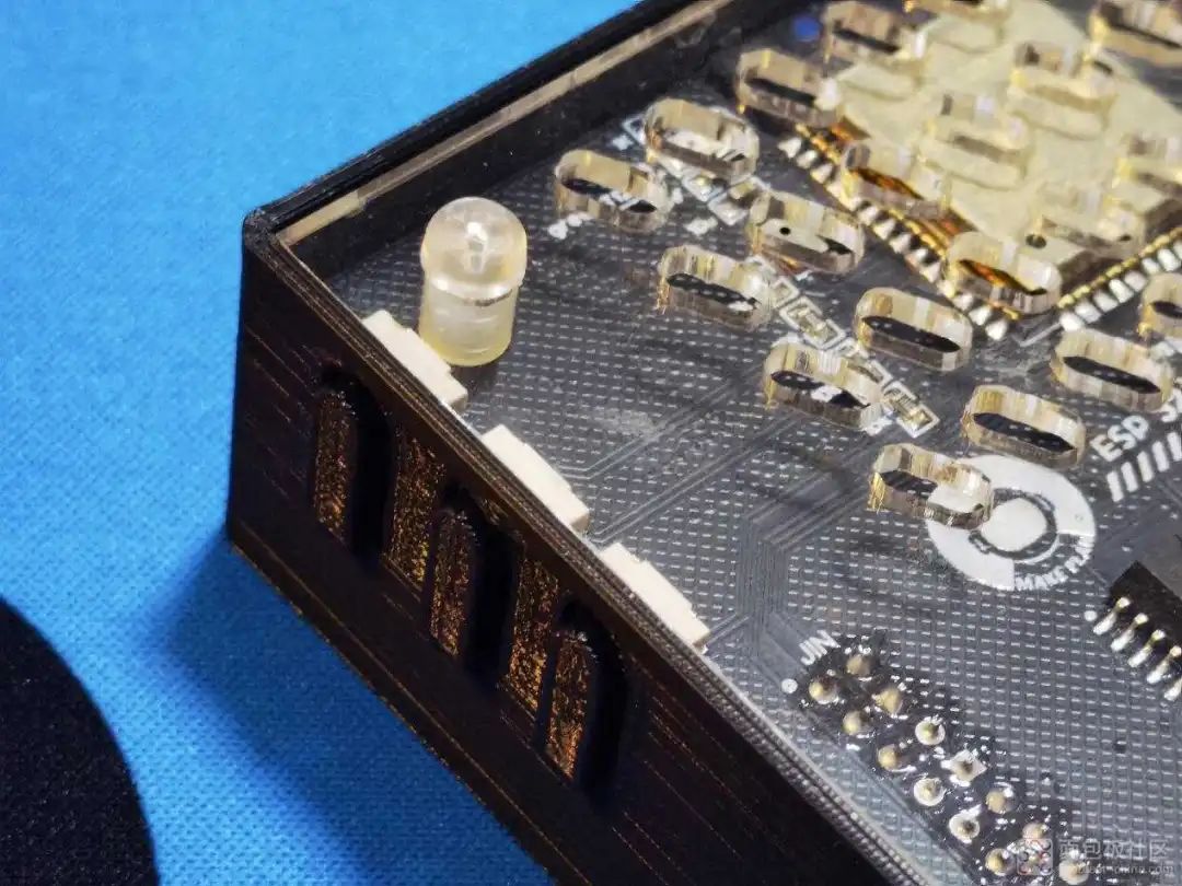
Zooming in on the details shows the plastic pillar and the heat dissipation holes, as well as the side-mounted tactile buttons.
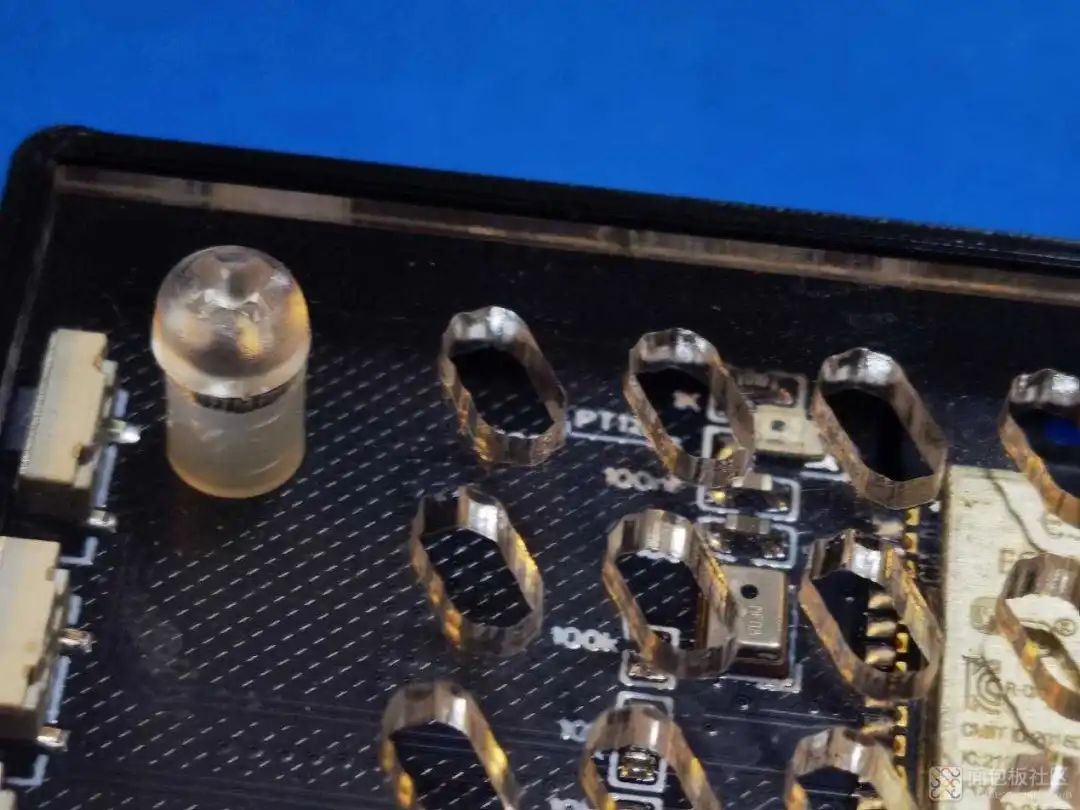
Removing the screws reveals transparent plastic material. The strength may not be high, but it is sufficient for practical use.
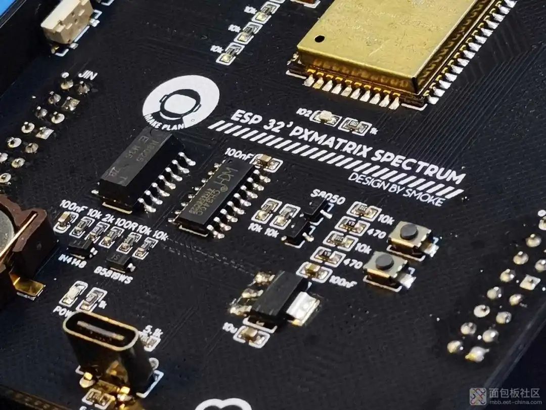
After removing the acrylic cover, we can see a Type C interface and the printed 512 resistor.
From another angle, the overall layout and wiring still feel good.

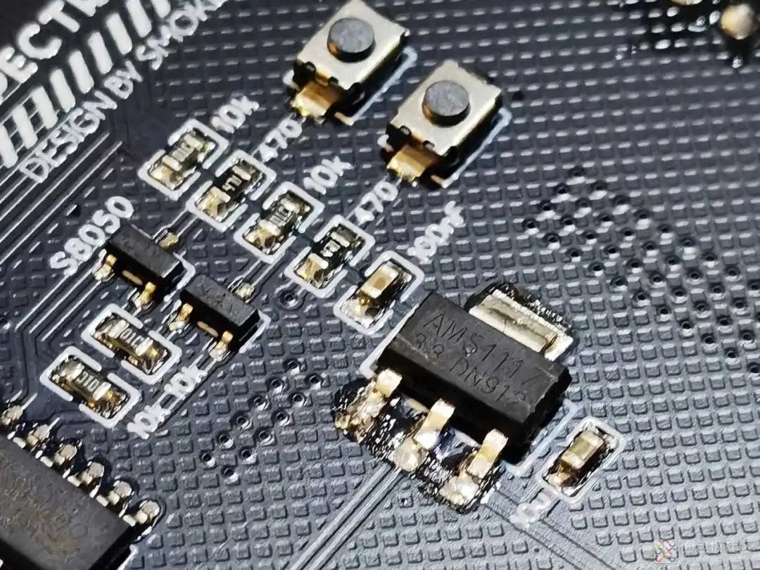
Next to the Type C interface is an ASM1117-3.3, which converts 5V power supply to 3.3V. Next to it are two buttons, one for reset and one for boot programming.

Next is the CH340C from Qinheng, a commonly used USB to serial chip, onboard to achieve one-click programming when the USB data line is plugged in.
Next is the main control chip module, the Espressif ESP32-WROOM, an integrated module with WiFi, Bluetooth, and low-power Bluetooth, with a silicon microphone next to it for audio pickup.

Let’s take another look at these chips from a different angle.
After removing the mainboard, we can see that there are almost no components on the back of the mainboard, only a pin header socket for connection.
After removing the mainboard, the light board is revealed; as expected, not using a single-wire LED bead solution requires many driver chips to control the LEDs.

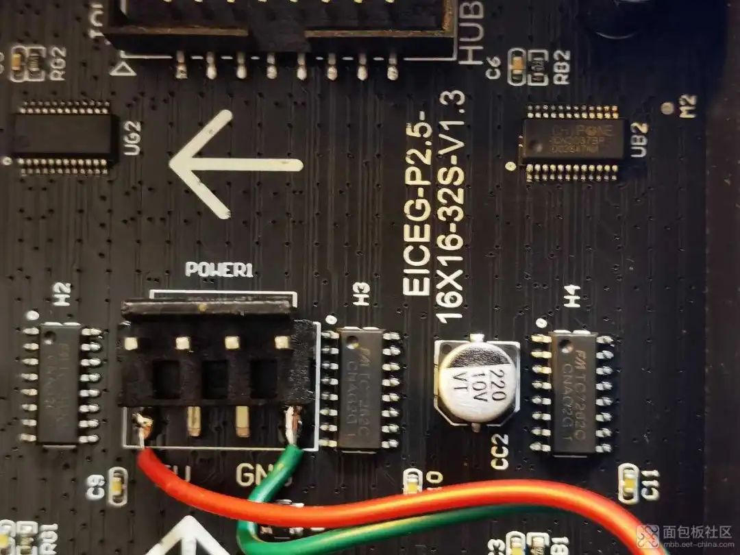
The light board has a power interface, and to make it convenient, wires are directly soldered down; the horn seats on both sides are data interfaces.
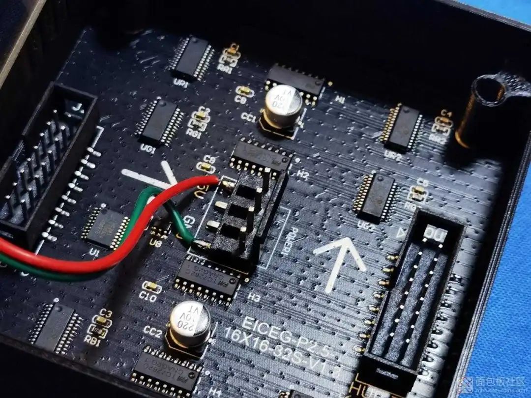
It can be seen that the TC7262C, an 8-channel LED display driver chip from Fuman Micro, and the ICN2037, a constant current LED driver IC from Jichuang Beifang, are used.
The back uses many driver chips for cascading.

This allows for control of the entire display.

This is the entire disassembly process, which is very simple overall; the light screen part and the main control part, the hardware is not difficult, but the difficulty lies in the excellent algorithms and network control.
So, do you want such a cool spectrum light?
Author: Maruko~, Source: Breadboard Community [Write Disassembly, Win Drone Event]

Event Theme
Electronic Disassembly
Participation Method
1. You need to publish the article with images in the Breadboard Community’s “Disassembly Base” section or “Blog” with the title: [Disassembly] + …2. You can participate in video form, published in the Breadboard Community’s “Core Video” section, with the title: [Disassembly] + …
👇Scan the code to directly access the community to publish articles/videos

Event Rewards
Over Ten Thousand Rewards: If a single article/video reaches over ten thousand views on the MBB WeChat account, an additional 5000 E coins will be rewarded for each article. (E coins can be exchanged for prizes in the Breadboard Community Mall; data statistics are valid until 2024.10.31, limited to the first 20 articles, sorted by the time of publication in the MBB community)
Join the Community
You can scan the code to add the community assistant on WeChat. If you encounter any issues, please contact us in time.

👇Click to read the original text and participate in the event!
Event Theme
Electronic Disassembly