Click on “ Jicheng Training ” above, select “Pin to Top”
160,000+ industrial control professionals follow this WeChat platform: technical sharing, learning exchange, industrial control videos
In the Omron PLC system, the units occupy different addresses in the CIO area according to their front and back positions or special characteristics. Understanding address allocation and knowing the specific storage locations of input and output data allows for correct data processing through programming.
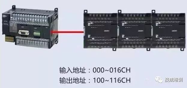
In the I/O memory, the CPU unit and CP1W extension unit occupy input addresses from channel 000 to 016, while output addresses occupy channels 100 to 116. One channel corresponds to one word, which is equal to 16 bits. In this article, we will use the CP1H as an example to explain the rules of PLC address allocation.
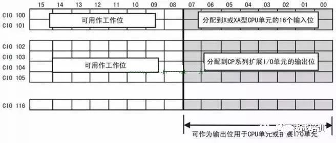
 1. CPU Unit Address Allocation: The X and XA type CPU units come with 40 points of I/O, including 24 input points and 16 output points. In the CIO area, the input part occupies channels 0 to 1, allocating a total of 24 input bits: ① 12 bits are from channel 0, bits 00 to 11
② Another 12 bits are from channel 1, bits 00 to 11
③ The unused bits 12 to 15 in channels 0 and 1 will always be cleared and cannot be used as internal auxiliary working bits
The output of the X and XA type CPU units has 16 points, occupying channels 100 to 101 in the CIO area, allocating a total of 16 output bits:
① 8 bits are from channel 100, bits 00 to 07
② Another 8 bits are from channel 101, bits 00 to 07. ③ The bits 08 to 15 in channels 100 and 101 can be used as internal auxiliary working bits
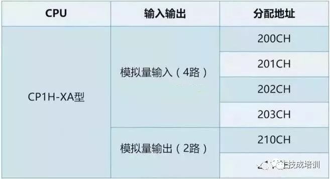
The CP1H-XA type CPU has built-in analog input and output, where 4 channels of analog input occupy channels 200 to 203, and 2 channels of analog output occupy channels 210 to 211.
 Y type CPU: The CP1H-Y type CPU has 20 points of I/O, including 12 input points and 8 output points. Due to the dedicated terminals for pulse input and output, the input and output are allocated to non-continuous addresses: ① Therefore, the input of the Y type CPU unit occupies a total of 12 points in channels 0 and 1 of the CIO area. ② The unused bits 12 to 15 in channels 0 and 1 will always be cleared and cannot be used as internal auxiliary working bits
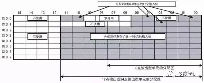
The output of the Y type CPU unit has 8 points, also due to the dedicated terminals for pulse input and output:
① The outputs of the CPU unit occupy a total of 8 points in channels 100 and 101 of the CIO area
② The unused bits 08 to 15 in channels 100 and 101 can be used as internal auxiliary working bits
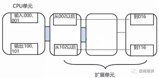
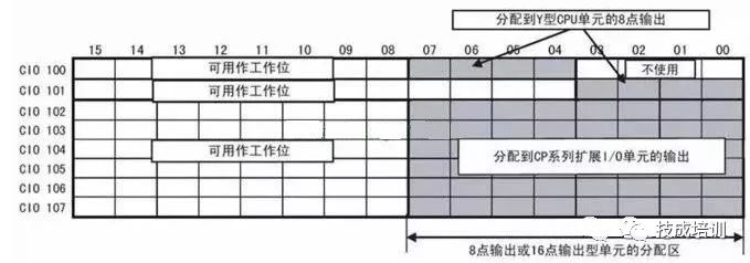 2. Extension Unit Address Allocation: The function of the extension unit is to expand inputs and outputs. The extension unit starts allocating addresses from the next channel after the allocation channels of the CPU unit, sequentially allocating addresses. The CP1W extension unit, like the CPU unit, has built-in inputs occupying channels 0 and 1, and outputs occupying channels 100 and 101. The subsequent connected CP1W extension units:
① Their inputs start from channel 2 and are allocated sequentially, with a maximum allocation to channel 16. ② Outputs start from channel 102 and are allocated sequentially, with a maximum allocation to channel 116
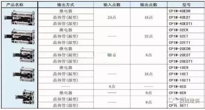
 The basic I/O extension unit of CP1W allocates different input and output channels based on the number of points. The bit allocation principle is the same as that of the CPU unit’s input and output allocation. For example, a 12-point input and 8-point output extension unit occupies 1 channel each:
① Its input bits occupy bits 00 to 11 of the allocated channel, and the unused bits 12 to 15 will always be cleared and cannot be used as internal auxiliary working bits. ② The output bits occupy bits 00 to 07 of the allocated channel, and the unused bits 08 to 15 can be used as internal auxiliary working bits
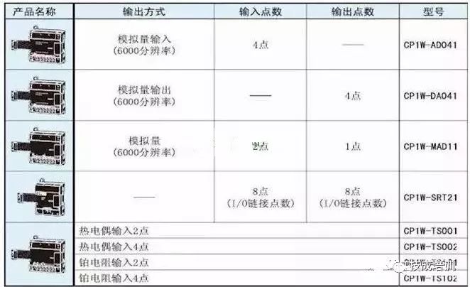
For expansion units such as analog and temperature sensors, the addresses of the input and output channels are allocated based on the number of channels occupied. For example, CP1W-MAD11 allocates 2 input channels and 1 output channel.
CJ Series High-Function Expansion Unit
The address allocation of the CJ series high-function expansion unit is related to its unit number, which is a hardware switch on the module. Special I/O units occupy addresses from channels 2000 to 2959 according to their arrangement, as shown in the figure below:

The CPU bus unit occupies addresses from channels 1500 to 1899 according to their arrangement, as shown in the figure below:

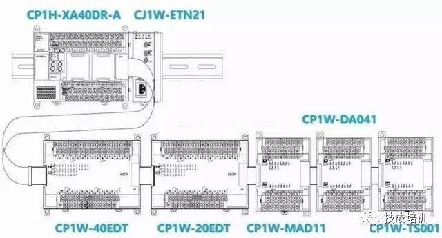
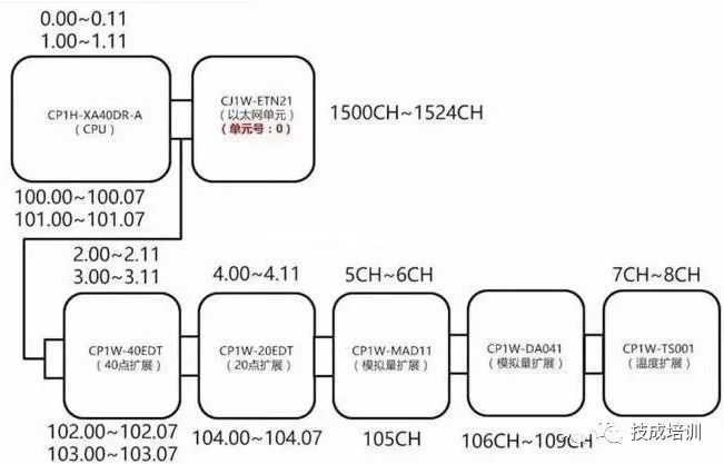
3. Application Example: As shown in the figure, the CP1H PLC is configured with 1 Ethernet module, 2 basic I/O extension units, 2 analog extension units, and 1 temperature sensor unit. How are the addresses of each input and output allocated?
The correct answer is as follows:
Share in Moments, Let’s Learn Together!
ClickRead Original to learn about electrical engineering, PLC, frequency servo, CNC robots, and more.