Overview:The I2C communication interface is one of the most commonly used MCU peripherals in our daily applications. Initially, before MCUs had hardware I2C, I2C communication was accomplished by simulating I2C timing through GPIO ports. Later, as MCUs began to include I2C peripheral interfaces, the use of hardware I2C became commonplace. More importantly, this not only saves MCU resources but also simplifies and enhances usability. Subsequently, due to changes in market demand, MCUs began to support I2C multi-slave address communication, allowing I2C applications to keep pace with market needs.
Although it is known from the characteristics of I2C that devices with different I2C addresses can be mounted on the same I2C bus for communication, what if there is an address conflict among the I2C devices that need to be operated? What if the number of hardware I2C interfaces on the MCU is insufficient? Or if the MCU’s I2C does not support multi-address communication for slaves? In such cases, we still need to simulate I2C timing through GPIO ports to achieve the functionality of I2C master/slave. Therefore, the existence of hardware I2C does not eliminate the need for software I2C; rather, software and hardware implementations coexist and complement each other.
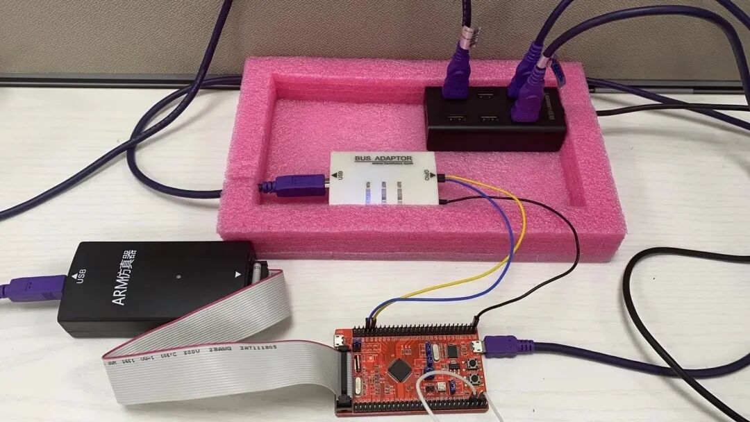
For the basic concepts and timing of I2C, this article will not describe in detail. You can download the “I2C Bus Overview” and “I2C Bus Specification” in the attachment for study.This article will discuss the implementation of I2C on the MM32F032/MM32F0140 series MCUs from the following four aspects, as well as practical testing using I2C tools (Timos USB2XXX bus adapter):
- Hardware I2C Master Communication
- Software Simulated I2C Master Communication
- Hardware I2C Slave Communication
- Software Simulated I2C Slave Communication (with difficulty)
The MM32F032 series MCU has one hardware I2C interface, supporting two operating speed modes: standard mode (data transfer rate of 0~100kbps) and fast mode (maximum data transfer rate of 400kbps). Its main features are as follows:
- I2C bus protocol converter/parallel bus;
- Half-duplex synchronous operation;
- Supports master/slave mode;
- Supports 7-bit and 10-bit addresses;
- Supports standard mode 100kbps and fast mode 400kbps;
- Generates Start, Stop, Repeated Start, and Acknowledge signal detection;
- Only one master is supported in master mode;
- Has separate 2-byte transmit and receive buffers;
- Includes glitch-free circuits on SCL and SDA;
- Supports DAM, interrupt, and polling operation modes;
- The MM32F0140 series MCU has richer I2C functionalities based on the MM32F032, supporting multi-slave address communication and clock stretching, etc. For specifics, please refer to the official datasheet.
1. Hardware I2C Master Communication
The hardware I2C of MM32 is the simplest to operate in code segments I have used so far; there is no need to consider START signals, ACK signals, or various EVENT events… These complex operations, or operations that can be omitted, are implemented by the official low-level library and chip IP, simplifying our design of driver programs.For the configuration of the hardware I2C master, we only need the reused GPIO port pins, I2C communication parameters, and slave address; then we can program to read and write to the I2C slave device. The initialization configuration and implementation code for reading and writing to the I2C slave device is as follows:
void hI2C_MASTER_Init(uint8_t SlaveAddress){    GPIO_InitTypeDef GPIO_InitStructure;    I2C_InitTypeDef  I2C_InitStructure;
    RCC_APB1PeriphClockCmd(RCC_APB1ENR_I2C1, ENABLE);
    I2C_StructInit(&I2C_InitStructure);    I2C_InitStructure.I2C_Mode       = I2C_Mode_MASTER;    I2C_InitStructure.I2C_OwnAddress = 0;    I2C_InitStructure.I2C_Speed      = I2C_Speed_STANDARD;    I2C_InitStructure.I2C_ClockSpeed = 100000;    I2C_Init(I2C1, &I2C_InitStructure);
    I2C_Send7bitAddress(I2C1, SlaveAddress, I2C_Direction_Transmitter);    I2C_Cmd(I2C1, ENABLE);
    RCC_AHBPeriphClockCmd(RCC_AHBENR_GPIOB, ENABLE);
    GPIO_PinAFConfig(GPIOB, GPIO_PinSource6, GPIO_AF_1);    GPIO_PinAFConfig(GPIOB, GPIO_PinSource7, GPIO_AF_1);
    GPIO_StructInit(&GPIO_InitStructure);    GPIO_InitStructure.GPIO_Pin   = GPIO_Pin_6 | GPIO_Pin_7;    GPIO_InitStructure.GPIO_Speed = GPIO_Speed_2MHz;    GPIO_InitStructure.GPIO_Mode  = GPIO_Mode_AF_OD;    GPIO_Init(GPIOB, &GPIO_InitStructure);}
void hI2C_MASTER_Read(uint8_t Address, uint8_t *Buffer, uint8_t Length){    uint8_t flag = 0, count = 0;
    I2C_SendData(I2C1, Address);    while(!I2C_GetFlagStatus(I2C1, I2C_STATUS_FLAG_TFE));
    for(uint8_t i = 0; i < Length; i++)    {        while(1)        {            if((I2C_GetFlagStatus(I2C1, I2C_STATUS_FLAG_TFNF)) && (flag == 0))            {                I2C_ReadCmd(I2C1);   count++;                if(count == Length) flag = 1;            }
            if(I2C_GetFlagStatus(I2C1, I2C_STATUS_FLAG_RFNE))            {                Buffer[i] = I2C_ReceiveData(I2C1);     break;            }        }    }
    I2C_GenerateSTOP(I2C1, ENABLE);    while(!I2C_GetFlagStatus(I2C1, I2C_FLAG_STOP_DET));}
void hI2C_MASTER_Write(uint8_t Address, uint8_t *Buffer, uint8_t Length){    I2C_SendData(I2C1, Address);    while(!I2C_GetFlagStatus(I2C1, I2C_STATUS_FLAG_TFE));
    for(uint8_t i = 0; i < Length; i++)    {        I2C_SendData(I2C1, *Buffer++);        while(!I2C_GetFlagStatus(I2C1, I2C_STATUS_FLAG_TFE));    }
    I2C_GenerateSTOP(I2C1, ENABLE);    while(!I2C_GetFlagStatus(I2C1, I2C_FLAG_STOP_DET));}
void hI2C_MASTER_SHELL_Handler(uint8_t Mode){    uint8_t Buffer[10] = {0x12, 0x23, 0x34, 0x45, 0x56, 0x67, 0x78, 0x89, 0x90, 0xAA};
    if(Mode == 1)    {        hI2C_MASTER_Write(0x00, Buffer, sizeof(Buffer));    }    else    {        hI2C_MASTER_Read(0x00, Buffer, sizeof(Buffer));
        printf("\r\nhI2C Master Read : \r\n");
        for(uint8_t i = 0; i < sizeof(Buffer); i++)        {            printf("0x%02x ", Buffer[i]);        }
        printf("\r\n");    }}
SHELL_EXPORT_CMD(HI2C_MASTER, hI2C_MASTER_SHELL_Handler, Hardware I2C Master Read And Write);
The actual test results are as follows: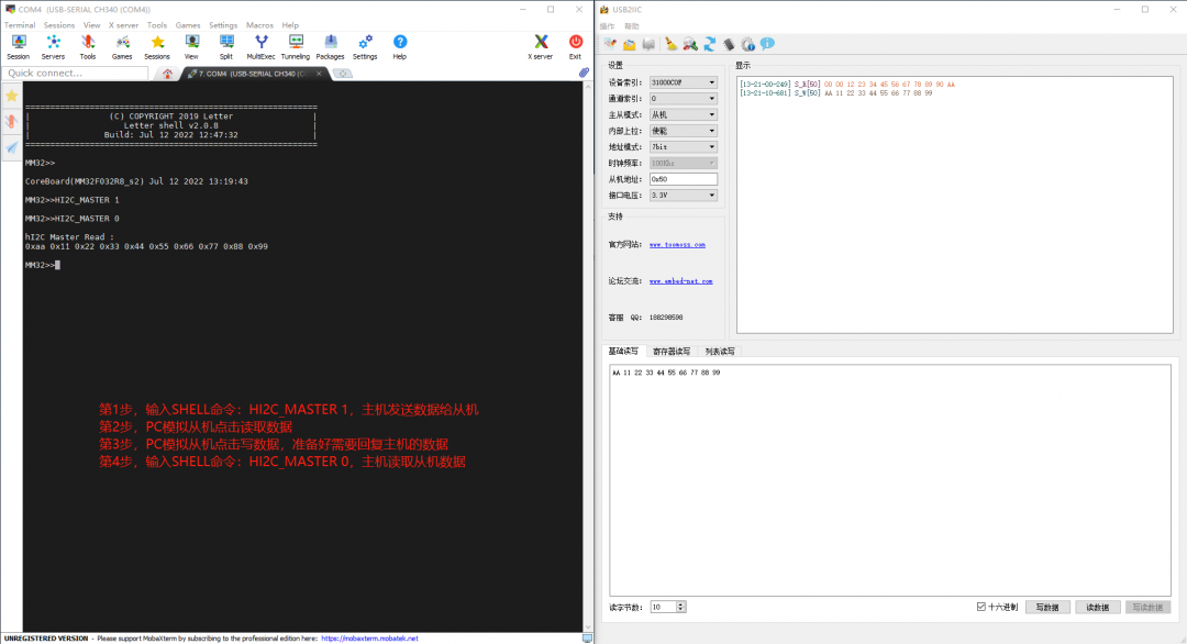
2. Software Simulated I2C Master Communication
The implementation of software simulated I2C master communication mainly involves manipulating the high and low levels of GPIO port pins to meet the timing requirements of I2C communication for reading and writing to I2C slave devices. When implementing software simulated I2C master, it is necessary to correctly generate Start conditions, Stop conditions, and Restart conditions; configure the input and output states of GPIO port pins at appropriate positions to correctly determine ACK and NACK response signals; and correctly operate the byte format being sent so that address and data content can be correctly recognized…
The following software simulated I2C master implementation defines an operation structure, allowing the software simulated I2C master program to achieve object-oriented programming by passing operation instances. This way, multiple software simulated I2C master communication interfaces can be implemented using the same code, greatly saving space in the code and making the code’s portability more universal.The specific code implementation is as follows:
typedef struct{    uint32_t      SCL_RCC;    GPIO_TypeDef *SCL_GPIO;    uint16_t      SCL_PIN;
    uint32_t      SDA_RCC;    GPIO_TypeDef *SDA_GPIO;    uint16_t      SDA_PIN;
    uint32_t      TIME;    uint8_t       SlaveAddress;} sI2C_MASTER_TypeDef;

sI2C_MASTER_TypeDef sI2C_MASTER = {    RCC_AHBENR_GPIOB, GPIOB, GPIO_Pin_6,    RCC_AHBENR_GPIOB, GPIOB, GPIO_Pin_7,    100,    0xA0};

#define sI2C_MASTER_SCL_H(sI2C)     GPIO_WriteBit(sI2C->SCL_GPIO, sI2C->SCL_PIN, Bit_SET)
#define sI2C_MASTER_SCL_L(sI2C)     GPIO_WriteBit(sI2C->SCL_GPIO, sI2C->SCL_PIN, Bit_RESET)
#define sI2C_MASTER_SDA_H(sI2C)     GPIO_WriteBit(sI2C->SDA_GPIO, sI2C->SDA_PIN, Bit_SET)
#define sI2C_MASTER_SDA_L(sI2C)     GPIO_WriteBit(sI2C->SDA_GPIO, sI2C->SDA_PIN, Bit_RESET)
#define sI2C_MASTER_SCL_GET(sI2C)   GPIO_ReadOutputDataBit(sI2C->SCL_GPIO, sI2C->SCL_PIN)
#define sI2C_MASTER_SDA_GET(sI2C)   GPIO_ReadInputDataBit( sI2C->SDA_GPIO, sI2C->SDA_PIN)

void sI2C_MASTER_Delay(uint32_t Tick){    while(Tick--);}
void sI2C_MASTER_SDA_SetDirection(sI2C_MASTER_TypeDef *sI2C, uint8_t Direction){    GPIO_InitTypeDef GPIO_InitStructure;
    RCC_AHBPeriphClockCmd(sI2C->SDA_RCC, ENABLE);
    GPIO_StructInit(&GPIO_InitStructure);    GPIO_InitStructure.GPIO_Pin   = sI2C->SDA_PIN;    GPIO_InitStructure.GPIO_Speed = GPIO_Speed_50MHz;
    if(Direction)   /* Input */    {        GPIO_InitStructure.GPIO_Mode  = GPIO_Mode_IN_FLOATING;    }    else            /* Output */    {        GPIO_InitStructure.GPIO_Mode  = GPIO_Mode_Out_PP;    }
    GPIO_Init(sI2C->SDA_GPIO, &GPIO_InitStructure);}
void sI2C_MASTER_SCL_SetDirection(sI2C_MASTER_TypeDef *sI2C, uint8_t Direction){    GPIO_InitTypeDef GPIO_InitStructure;
    RCC_AHBPeriphClockCmd(sI2C->SCL_RCC, ENABLE);
    GPIO_StructInit(&GPIO_InitStructure);    GPIO_InitStructure.GPIO_Pin   = sI2C->SCL_PIN;    GPIO_InitStructure.GPIO_Speed = GPIO_Speed_50MHz;
    if(Direction)   /* Input */    {        GPIO_InitStructure.GPIO_Mode  = GPIO_Mode_IN_FLOATING;    }    else            /* Output */    {        GPIO_InitStructure.GPIO_Mode  = GPIO_Mode_Out_PP;    }
    GPIO_Init(sI2C->SCL_GPIO, &GPIO_InitStructure);}
void sI2C_MASTER_GenerateStart(sI2C_MASTER_TypeDef *sI2C){    sI2C_MASTER_SDA_H(sI2C); sI2C_MASTER_Delay(sI2C->TIME);    sI2C_MASTER_SCL_H(sI2C); sI2C_MASTER_Delay(sI2C->TIME);    sI2C_MASTER_SDA_L(sI2C); sI2C_MASTER_Delay(sI2C->TIME);    sI2C_MASTER_SCL_L(sI2C); sI2C_MASTER_Delay(sI2C->TIME);}
void sI2C_MASTER_GenerateStop(sI2C_MASTER_TypeDef *sI2C){    sI2C_MASTER_SDA_L(sI2C); sI2C_MASTER_Delay(sI2C->TIME);    sI2C_MASTER_SCL_H(sI2C); sI2C_MASTER_Delay(sI2C->TIME);    sI2C_MASTER_SDA_H(sI2C); sI2C_MASTER_Delay(sI2C->TIME);}
void sI2C_MASTER_PutACK(sI2C_MASTER_TypeDef *sI2C, uint8_t ack){    if(ack) sI2C_MASTER_SDA_H(sI2C);    /* NACK */    else    sI2C_MASTER_SDA_L(sI2C);    /* ACK  */
    sI2C_MASTER_Delay(sI2C->TIME);
    sI2C_MASTER_SCL_H(sI2C); sI2C_MASTER_Delay(sI2C->TIME);    sI2C_MASTER_SCL_L(sI2C); sI2C_MASTER_Delay(sI2C->TIME);}
uint8_t sI2C_MASTER_GetACK(sI2C_MASTER_TypeDef *sI2C){    uint8_t ack = 0;
    sI2C_MASTER_SDA_H(sI2C); sI2C_MASTER_Delay(sI2C->TIME);
    sI2C_MASTER_SDA_SetDirection(sI2C, 1);
    sI2C_MASTER_SCL_H(sI2C); sI2C_MASTER_Delay(sI2C->TIME);
    ack = sI2C_MASTER_SDA_GET(sI2C);
    sI2C_MASTER_SCL_L(sI2C); sI2C_MASTER_Delay(sI2C->TIME);
    sI2C_MASTER_SDA_SetDirection(sI2C, 0);
    return ack;}
uint8_t sI2C_MASTER_ReadByte(sI2C_MASTER_TypeDef *sI2C){    uint8_t Data = 0;
    sI2C_MASTER_SDA_H(sI2C); /* Must set SDA before read */
    sI2C_MASTER_SDA_SetDirection(sI2C, 1);
    for(uint8_t i = 0; i < 8; i++)    {        sI2C_MASTER_SCL_H(sI2C); sI2C_MASTER_Delay(sI2C->TIME);
        Data <<= 1;
        if(sI2C_MASTER_SDA_GET(sI2C)) Data |= 0x01;
        sI2C_MASTER_SCL_L(sI2C); sI2C_MASTER_Delay(sI2C->TIME);    }
    sI2C_MASTER_SDA_SetDirection(sI2C, 0);
    return Data;}
void sI2C_MASTER_WriteByte(sI2C_MASTER_TypeDef *sI2C, uint8_t Data){    for(uint8_t i = 0; i < 8; i++)    {        if(Data & 0x80) sI2C_MASTER_SDA_H(sI2C);        else            sI2C_MASTER_SDA_L(sI2C);
        Data <<= 1;
        sI2C_MASTER_SCL_H(sI2C); sI2C_MASTER_Delay(sI2C->TIME);        sI2C_MASTER_SCL_L(sI2C); sI2C_MASTER_Delay(sI2C->TIME);    }}
void sI2C_MASTER_Init(sI2C_MASTER_TypeDef *sI2C){    sI2C_MASTER_SDA_SetDirection(sI2C, 0);    sI2C_MASTER_SCL_SetDirection(sI2C, 0);
    sI2C_MASTER_SCL_H(sI2C); sI2C_MASTER_Delay(sI2C->TIME);    sI2C_MASTER_SDA_H(sI2C); sI2C_MASTER_Delay(sI2C->TIME);}
uint8_t sI2C_MASTER_Read(sI2C_MASTER_TypeDef *sI2C, uint8_t Address, uint8_t *Buffer, uint8_t Length){    if(Length == 0) return 0;
    sI2C_MASTER_GenerateStart(sI2C);
    sI2C_MASTER_WriteByte(sI2C, sI2C->SlaveAddress);
    if(sI2C_MASTER_GetACK(sI2C))    {        sI2C_MASTER_GenerateStop(sI2C); return 1;    }
    sI2C_MASTER_WriteByte(sI2C, Address);
    if(sI2C_MASTER_GetACK(sI2C))    {        sI2C_MASTER_GenerateStop(sI2C); return 1;    }
    sI2C_MASTER_GenerateStart(sI2C);
    sI2C_MASTER_WriteByte(sI2C, sI2C->SlaveAddress + 1);
    if(sI2C_MASTER_GetACK(sI2C))    {        sI2C_MASTER_GenerateStop(sI2C); return 1;    }
    while(1)    {        *Buffer++ = sI2C_MASTER_ReadByte(sI2C);
        if(--Length == 0)        {            sI2C_MASTER_PutACK(sI2C, 1); break;        }
        sI2C_MASTER_PutACK(sI2C, 0);    }
    sI2C_MASTER_GenerateStop(sI2C);
    return 0;}
uint8_t sI2C_MASTER_Write(sI2C_MASTER_TypeDef *sI2C, uint8_t Address, uint8_t *Buffer, uint8_t Length){    uint8_t i = 0;
    if(Length == 0) return 0;
    sI2C_MASTER_GenerateStart(sI2C);
    sI2C_MASTER_WriteByte(sI2C, sI2C->SlaveAddress);
    if(sI2C_MASTER_GetACK(sI2C))    {        sI2C_MASTER_GenerateStop(sI2C); return 1;    }
    sI2C_MASTER_WriteByte(sI2C, Address);
    if(sI2C_MASTER_GetACK(sI2C))    {        sI2C_MASTER_GenerateStop(sI2C); return 1;    }
    for(i = 0; i < Length; i++)    {        sI2C_MASTER_WriteByte(sI2C, *Buffer++);
        if(sI2C_MASTER_GetACK(sI2C))     break;    }
    sI2C_MASTER_GenerateStop(sI2C);
    if(i == Length) return 0;    else            return 1;}
void sI2C_MASTER_SHELL_Handler(uint8_t Mode){    uint8_t Buffer[10] = {0x11, 0x22, 0x33, 0x44, 0x55, 0xAA, 0xBB, 0xCC, 0xDD, 0xEE};
    if(Mode == 1)    {        sI2C_MASTER_Write(&sI2C_MASTER, 0x00, Buffer, sizeof(Buffer));    }    else    {        sI2C_MASTER_Read(&sI2C_MASTER, 0x00, Buffer, sizeof(Buffer));
        printf("\r\nsI2C Master Read : \r\n");
        for(uint8_t i = 0; i < sizeof(Buffer); i++)        {            printf("0x%02x ", Buffer[i]);        }
        printf("\r\n");    }}
SHELL_EXPORT_CMD(SI2C_MASTER, sI2C_MASTER_SHELL_Handler, Software I2C Master Read And Write);
The actual test results are as follows: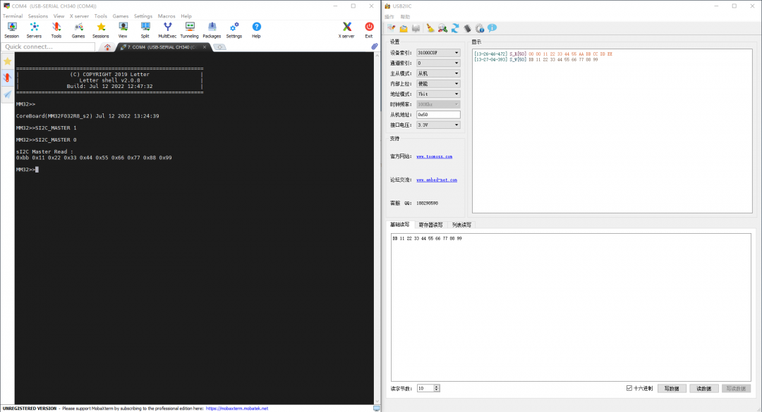
3. Hardware I2C Slave Communication
For hardware I2C slave communication, an interrupt response method is often used to avoid the program waiting indefinitely for I2C master operations; polling methods can easily miss I2C requests or events. Therefore, the following hardware I2C slave communication method uses interrupt handling, where any operation and request from the I2C master will trigger the corresponding interrupt. Once the slave detects this, it enters the interrupt to perform the corresponding processing, and the interrupt method also ensures normal and stable communication.
Many MCUs on the market support multi-address mode for I2C slave mode, but the IP function design varies by manufacturer: some allow setting the slave address directly through registers, which limits the number of supported slave addresses; others use address masking (similar to CAN communication ID filters) to determine supported I2C slave addresses through bitwise comparison, allowing for many slave addresses. The second method is more flexible than the first, supporting more slave device addresses!
The MM32F032 does not support multi-address slave functionality, but the MM32F0140 supports multi-address communication for slaves, allowing you to choose the appropriate chip model based on actual project needs. The multi-address functionality for slaves uses address masking to filter slave addresses, thus supporting more slave device addresses. This is achieved by setting the slave device address and the slave address mask to implement multi-address communication for slaves.The specific code implementation for hardware I2C slave communication is as follows:
void hI2C_SLAVE_Init(uint8_t SlaveAddress){    I2C_InitTypeDef  I2C_InitStructure;    GPIO_InitTypeDef GPIO_InitStructure;    NVIC_InitTypeDef NVIC_InitStructure;
    QUEUE_INIT(QUEUE_HI2C_SLAVE_IDX);
    RCC_APB1PeriphClockCmd(RCC_APB1ENR_I2C1, ENABLE);
    I2C_StructInit(&I2C_InitStructure);    I2C_InitStructure.Mode       = I2C_Mode_SLAVE;    I2C_InitStructure.OwnAddress = 0;    I2C_InitStructure.Speed      = I2C_Speed_FAST;    I2C_InitStructure.ClockSpeed = 400000;    I2C_Init(I2C1, &I2C_InitStructure);
    I2C_ITConfig(I2C1, I2C_IT_RD_REQ,  ENABLE);    I2C_ITConfig(I2C1, I2C_IT_RX_FULL, ENABLE);
    I2C_Cmd(I2C1, ENABLE);
    RCC_AHBPeriphClockCmd(RCC_AHBENR_GPIOB, ENABLE);
    GPIO_PinAFConfig(GPIOB, GPIO_PinSource6, GPIO_AF_1);    GPIO_PinAFConfig(GPIOB, GPIO_PinSource7, GPIO_AF_1);
    GPIO_StructInit(&GPIO_InitStructure);    GPIO_InitStructure.GPIO_Pin   = GPIO_Pin_6;    GPIO_InitStructure.GPIO_Speed = GPIO_Speed_50MHz;    GPIO_InitStructure.GPIO_Mode  = GPIO_Mode_FLOATING;    GPIO_Init(GPIOB, &GPIO_InitStructure);
    GPIO_StructInit(&GPIO_InitStructure);    GPIO_InitStructure.GPIO_Pin   = GPIO_Pin_7;    GPIO_InitStructure.GPIO_Speed = GPIO_Speed_50MHz;    GPIO_InitStructure.GPIO_Mode  = GPIO_Mode_AF_OD;    GPIO_Init(GPIOB, &GPIO_InitStructure);
    NVIC_InitStructure.NVIC_IRQChannel = I2C1_IRQn;    NVIC_InitStructure.NVIC_IRQChannelPriority = 0;    NVIC_InitStructure.NVIC_IRQChannelCmd = ENABLE;    NVIC_Init(&NVIC_InitStructure);
    I2C_SendSlaveAddress(I2C1, SlaveAddress);}
void I2C1_IRQHandler(void){    static uint8_t Data = 0;
    if(I2C_GetITStatus(I2C1, I2C_IT_RD_REQ)  != RESET)    {        I2C_ClearITPendingBit(I2C1, I2C_IT_RD_REQ);
        while(1)        {            I2C_SendData(I2C1, Data++);            while(I2C_GetFlagStatus(I2C1, I2C_FLAG_TX_EMPTY) == RESET);
            if((Data % 10) == 0)            {                I2C_GenerateSTOP(I2C1, ENABLE); break;            }        }    }
    if(I2C_GetITStatus(I2C1, I2C_IT_RX_FULL) != RESET)    {        QUEUE_WRITE(QUEUE_HI2C_SLAVE_IDX, I2C_ReceiveData(I2C1));    }}
The actual test results are as follows: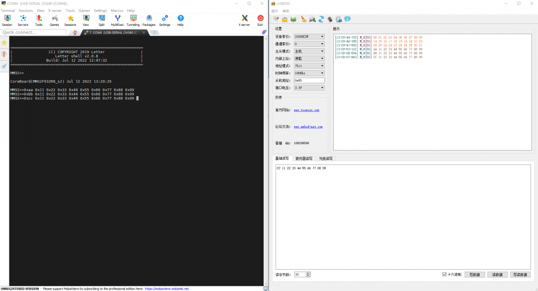
4. Software Simulated I2C Slave Communication
Software simulated I2C slave communication is the reverse implementation process of I2C communication timing. It requires capturing the I2C master’s signal timing to parse the master’s events, requests, and the data sent, while also correctly responding to the I2C master. Therefore, its implementation method is completely different from that of the I2C simulated master. This requires developers to be very familiar with I2C timing, so when studying the following software simulated I2C slave communication program, it is recommended to analyze it against the I2C timing step by step (Note: this part is somewhat challenging).
The implementation of software simulated I2C slave communication is achieved by connecting two GPIO port pins to the SCL and SDA of the I2C master, configuring these two GPIO port pins to work in external interrupt EXTI mode. By capturing the rising and falling edges and the high and low states of the GPIO port pins, combined with the state management of the software simulated I2C slave, communication functionality with the I2C master is realized. The following program includes detailed comments and explanations for easier reading and understanding. The specific code implementation is as follows:
typedef struct{    uint32_t      SCL_RCC;    GPIO_TypeDef *SCL_GPIO;    uint16_t      SCL_PIN;
    uint8_t       SCL_EXTI_PortSource;    uint8_t       SCL_EXTI_PinSource;    uint32_t      SCL_EXTI_Line;
    uint32_t      SDA_RCC;    GPIO_TypeDef *SDA_GPIO;    uint16_t      SDA_PIN;
    uint8_t       SDA_EXTI_PortSource;    uint8_t       SDA_EXTI_PinSource;    uint32_t      SDA_EXTI_Line;
    uint8_t       SlaveAddress;} sI2C_SLAVE_TypeDef;

sI2C_SLAVE_TypeDef sI2C_SLAVE = {    RCC_AHBENR_GPIOB, GPIOB, GPIO_Pin_6, EXTI_PortSourceGPIOB, EXTI_PinSource6, EXTI_Line6,    RCC_AHBENR_GPIOB, GPIOB, GPIO_Pin_7, EXTI_PortSourceGPIOB, EXTI_PinSource7, EXTI_Line7,    0xA0,};

#define sI2C_SLAVE_STATE_NA        0#define sI2C_SLAVE_STATE_STA       1#define sI2C_SLAVE_STATE_ADD       2#define sI2C_SLAVE_STATE_ADD_ACK   3#define sI2C_SLAVE_STATE_DAT       4#define sI2C_SLAVE_STATE_DAT_ACK   5#define sI2C_SLAVE_STATE_STO       6
uint8_t sI2C_SLAVE_State = sI2C_SLAVE_STATE_NA;
uint8_t sI2C_SLAVE_ShiftCounter = 0;uint8_t sI2C_SLAVE_SlaveAddress = 0;uint8_t sI2C_SLAVE_ReceivedData = 0;uint8_t sI2C_SLAVE_TransmitData = 0x50;
uint8_t sI2C_SLAVE_TransmitBuffer[16] = {    0x01, 0x12, 0x23, 0x34, 0x45, 0x56, 0x67, 0x78,    0x89, 0x9A, 0xAB, 0xBC, 0xCD, 0xDE, 0xEF, 0xF0,};uint8_t sI2C_SLAVE_TransmitIndex = 0;

bool sI2C_SLAVE_READ_SCL(sI2C_SLAVE_TypeDef *sI2C){    return GPIO_ReadInputDataBit(sI2C->SCL_GPIO, sI2C->SCL_PIN);}
bool sI2C_SLAVE_READ_SDA(sI2C_SLAVE_TypeDef *sI2C){    return GPIO_ReadInputDataBit(sI2C->SDA_GPIO, sI2C->SDA_PIN);}

/******************************************************************************* * [url=home.php?mod=space&uid=247401]@brief[/url]       Configure the GPIO ports for simulating I2C, default set to input mode, and enable the corresponding external trigger *              interrupt function (rising edge and falling edge) * @param        * @retval       * [url=home.php?mod=space&uid=93590]@Attention[/url]   *******************************************************************************/void sI2C_SLAVE_Init(sI2C_SLAVE_TypeDef *sI2C){    GPIO_InitTypeDef GPIO_InitStructure;    EXTI_InitTypeDef EXTI_InitStructure;    NVIC_InitTypeDef NVIC_InitStructure;
    RCC_AHBPeriphClockCmd(sI2C->SCL_RCC, ENABLE);    RCC_AHBPeriphClockCmd(sI2C->SDA_RCC, ENABLE);
    RCC_APB2PeriphClockCmd(RCC_APB2Periph_SYSCFG, ENABLE);
    GPIO_StructInit(&GPIO_InitStructure);    GPIO_InitStructure.GPIO_Pin   = sI2C->SCL_PIN;    GPIO_InitStructure.GPIO_Speed = GPIO_Speed_50MHz;    GPIO_InitStructure.GPIO_Mode  = GPIO_Mode_IN_FLOATING;    GPIO_Init(sI2C->SCL_GPIO, &GPIO_InitStructure);
    GPIO_StructInit(&GPIO_InitStructure);    GPIO_InitStructure.GPIO_Pin   = sI2C->SDA_PIN;    GPIO_InitStructure.GPIO_Speed = GPIO_Speed_50MHz;    GPIO_InitStructure.GPIO_Mode  = GPIO_Mode_IN_FLOATING;    GPIO_Init(sI2C->SDA_GPIO, &GPIO_InitStructure);
    SYSCFG_EXTILineConfig(sI2C->SCL_EXTI_PortSource, sI2C->SCL_EXTI_PinSource);
    EXTI_StructInit(&EXTI_InitStructure);    EXTI_InitStructure.EXTI_Line    = sI2C->SCL_EXTI_Line;    EXTI_InitStructure.EXTI_Mode    = EXTI_Mode_Interrupt;    EXTI_InitStructure.EXTI_Trigger = EXTI_Trigger_Rising_Falling;    EXTI_InitStructure.EXTI_LineCmd = ENABLE;    EXTI_Init(&EXTI_InitStructure);
    SYSCFG_EXTILineConfig(sI2C->SDA_EXTI_PortSource, sI2C->SDA_EXTI_PinSource);
    EXTI_StructInit(&EXTI_InitStructure);    EXTI_InitStructure.EXTI_Line    = sI2C->SDA_EXTI_Line;    EXTI_InitStructure.EXTI_Mode    = EXTI_Mode_Interrupt;    EXTI_InitStructure.EXTI_Trigger = EXTI_Trigger_Rising_Falling;    EXTI_InitStructure.EXTI_LineCmd = ENABLE;    EXTI_Init(&EXTI_InitStructure);
    NVIC_InitStructure.NVIC_IRQChannel = EXTI4_15_IRQn;    NVIC_InitStructure.NVIC_IRQChannelPriority  = 0x00;    NVIC_InitStructure.NVIC_IRQChannelCmd     = ENABLE;    NVIC_Init(&NVIC_InitStructure);}

/******************************************************************************* * [url=home.php?mod=space&uid=247401]@brief[/url]       Set the input/output direction of the SDA signal line, 0 represents Output, 1 represents Input * @param        * @retval       * [url=home.php?mod=space&uid=93590]@Attention[/url]   *******************************************************************************/void sI2C_SLAVE_SDA_SetDirection(sI2C_SLAVE_TypeDef *sI2C, uint8_t Direction){    GPIO_InitTypeDef GPIO_InitStructure;
    if(Direction)   /* Input */    {        GPIO_StructInit(&GPIO_InitStructure);        GPIO_InitStructure.GPIO_Pin   = sI2C->SDA_PIN;        GPIO_InitStructure.GPIO_Speed = GPIO_Speed_50MHz;        GPIO_InitStructure.GPIO_Mode  = GPIO_Mode_IN_FLOATING;        GPIO_Init(sI2C->SDA_GPIO, &GPIO_InitStructure);    }    else            /* Output */    {        GPIO_StructInit(&GPIO_InitStructure);        GPIO_InitStructure.GPIO_Pin   = sI2C->SDA_PIN;        GPIO_InitStructure.GPIO_Speed = GPIO_Speed_50MHz;        GPIO_InitStructure.GPIO_Mode  = GPIO_Mode_Out_OD;        GPIO_Init(sI2C->SDA_GPIO, &GPIO_InitStructure);    }}

/****************************************************************************** * @brief       Set the output level of the SDA signal line (high/low) * @param        * @retval       * @attention   ******************************************************************************/void sI2C_SLAVE_SDA_SetLevel(sI2C_SLAVE_TypeDef *sI2C, uint8_t Level){    sI2C_SLAVE_SDA_SetDirection(sI2C, 0);
    if(Level)    {        GPIO_WriteBit(sI2C->SDA_GPIO, sI2C->SDA_PIN, Bit_SET);    }    else    {        GPIO_WriteBit(sI2C->SDA_GPIO, sI2C->SDA_PIN, Bit_RESET);    }}

/****************************************************************************** * @brief       Handle the rising edge external interrupt when SCL triggers * @param        * @retval       * @attention   ******************************************************************************/void sI2C_SLAVE_SCL_RiseHandler(sI2C_SLAVE_TypeDef *sI2C){    /* SCL rising edge, data is locked, the master and slave get data bits from the SDA bus */    switch(sI2C_SLAVE_State)    {        case sI2C_SLAVE_STATE_ADD:
            /* I2C sends the address MSB, first send the high bit, then the low bit, so during reception, the data is left-shifted */
            sI2C_SLAVE_SlaveAddress <<= 1;            sI2C_SLAVE_ShiftCounter  += 1;
            if(sI2C_SLAVE_READ_SDA(sI2C) ==  Bit_SET)            {                sI2C_SLAVE_SlaveAddress |= 0x01;            }
            /* After receiving 8 bits of address, the slave needs to send an ACK response on the 9th clock */            if(sI2C_SLAVE_ShiftCounter == 8)            {                sI2C_SLAVE_State = sI2C_SLAVE_STATE_ADD_ACK;            }
            break;
        case sI2C_SLAVE_STATE_ADD_ACK:            /* After the ACK response to the slave address, switch to data transmission state */            sI2C_SLAVE_State = sI2C_SLAVE_STATE_DAT;
            sI2C_SLAVE_ShiftCounter = 0;    /* Clear data shift counter */            sI2C_SLAVE_ReceivedData = 0;    /* Clear received data */            break;
        case sI2C_SLAVE_STATE_DAT:            if((sI2C_SLAVE_SlaveAddress & 0x01) == 0x00)            {                /* Master write operation: the slave should get the SDA signal line level state sent by the master, and store the bit */                sI2C_SLAVE_ReceivedData <<= 1;                sI2C_SLAVE_ShiftCounter  += 1;
                if(sI2C_SLAVE_READ_SDA(sI2C) == Bit_SET)                {                    sI2C_SLAVE_ReceivedData |= 0x01;                }
                /* When a complete 8-bit data is received, store the received data in the I2C receive message queue, switch state to send ACK to the master */                if(sI2C_SLAVE_ShiftCounter == 8)                {                    QUEUE_WRITE(QUEUE_SI2C_SLAVE_IDX, sI2C_SLAVE_ReceivedData);
                    sI2C_SLAVE_ShiftCounter = 0;    /* Clear data shift counter */                    sI2C_SLAVE_ReceivedData = 0;    /* Clear received data */
                    sI2C_SLAVE_State = sI2C_SLAVE_STATE_DAT_ACK;                }            }            else            {                /* Master read operation: on the rising edge of the 8th data bit, the master will respond with ACK or NACK to the slave, so switch to waiting for ACK state, and prepare the next data to be sent */                if(sI2C_SLAVE_ShiftCounter == 8)                {                    sI2C_SLAVE_ShiftCounter = 0;    /* Clear received data */                    sI2C_SLAVE_TransmitData = sI2C_SLAVE_TransmitBuffer[sI2C_SLAVE_TransmitIndex++];
                    sI2C_SLAVE_TransmitIndex %= 16;
                    sI2C_SLAVE_State = sI2C_SLAVE_STATE_DAT_ACK;                }
            }
            break;
        case sI2C_SLAVE_STATE_DAT_ACK:            if((sI2C_SLAVE_SlaveAddress & 0x01) == 0x00)            {                /* Master write operation: the slave sends ACK, waiting for the master to read the ACK signal */
                sI2C_SLAVE_State = sI2C_SLAVE_STATE_DAT;  /* Switch to data reception state */            }            else            {                /* Master read operation: the master sends ACK, the slave can read the ACK signal sent by the master */
                uint8_t ack = sI2C_SLAVE_READ_SDA(sI2C);
                if(ack == Bit_RESET)                {                    sI2C_SLAVE_State = sI2C_SLAVE_STATE_DAT;    /* Received ACK, continue sending data */                }                else                {                    sI2C_SLAVE_State = sI2C_SLAVE_STATE_STO;    /* Received NACK, stop sending data */                }
            }
            break;
        default:            break;    }}

/****************************************************************************** * @brief       Handle the falling edge external interrupt when SCL triggers * @param        * @retval       * @attention   ******************************************************************************/void sI2C_SLAVE_SCL_FallHandler(sI2C_SLAVE_TypeDef *sI2C){    /* SCL falling edge, data can change */    switch(sI2C_SLAVE_State)    {        case sI2C_SLAVE_STATE_STA:            /*             * After detecting the START signal, the first falling edge of SCL indicates the start of transmission of the Slave Address,             * According to the rules of data validity, the first bit of the address must be read when SCL is high             * Switch to the state of obtaining Slave Address, waiting for the rising edge of SCL             */            sI2C_SLAVE_State = sI2C_SLAVE_STATE_ADD;
            sI2C_SLAVE_ShiftCounter = 0;    /* Clear data shift counter */            sI2C_SLAVE_SlaveAddress = 0;    /* Clear slave address */            sI2C_SLAVE_ReceivedData = 0;    /* Clear received data */            break;
        case sI2C_SLAVE_STATE_ADD:            /*             * When the master sends the Slave Address, the slave only reads the SDA state for address resolution, so no processing is done here             */            break;
        case sI2C_SLAVE_STATE_ADD_ACK:
            /* When SCL is low, send the address ACK signal to the I2C bus, state remains unchanged, waiting for the next rising edge to send ACK */
            sI2C_SLAVE_SDA_SetLevel(sI2C, 0);   /* Pull SDA low to send ACK signal to the master */            break;
        case sI2C_SLAVE_STATE_DAT:
            /* On the falling edge of the SCL clock signal, the SDA signal line can change state */
            if((sI2C_SLAVE_SlaveAddress & 0x01) == 0x00)            {                /* Master write operation: set the SDA signal line to input state, waiting for the next SCL rising edge to get data bit */                sI2C_SLAVE_SDA_SetDirection(sI2C, 1);            }            else            {                /* Master read operation: set the SDA signal line output level according to the data being sent, waiting for the next SCL rising edge to send data bit */
                if(sI2C_SLAVE_TransmitData & 0x80)                {                    sI2C_SLAVE_SDA_SetLevel(sI2C, 1);                }                else                {                    sI2C_SLAVE_SDA_SetLevel(sI2C, 0);                }
                sI2C_SLAVE_TransmitData <<= 1;                sI2C_SLAVE_ShiftCounter  += 1;            }
            break;
        case sI2C_SLAVE_STATE_DAT_ACK:
            /* Handle the falling edge of the 8th SCL clock signal */
            if((sI2C_SLAVE_SlaveAddress & 0x01) == 0x00)            {                /* Master write operation: after receiving data, the slave needs to send an ACK response to the master, state remains unchanged, waiting for the next rising edge to send ACK */
                sI2C_SLAVE_SDA_SetLevel(sI2C, 0);   /* Pull SDA low to send ACK signal to the master */            }            else            {                /* Master read operation: the slave needs to release the current SDA signal line for the master to send ACK or NACK to the slave, state remains unchanged, waiting for the next rising edge to read ACK signal */
                sI2C_SLAVE_SDA_SetDirection(sI2C, 1);            }
            break;
        default:            break;    }}

/**  * @brief  Handle the rising edge external interrupt when SDA triggers  * @param  None  * @retval None  */void sI2C_SLAVE_SDA_RiseHandler(sI2C_SLAVE_TypeDef *sI2C){    if(sI2C_SLAVE_READ_SCL(sI2C) == Bit_SET)    /* SCL is high, SDA is rising edge: STOP */    {        sI2C_SLAVE_State = sI2C_SLAVE_STATE_STO;    }    else                                        /* SCL is low, SDA is rising edge: data change */    {    }}

/**  * @brief  Handle the falling edge external interrupt when SDA triggers  * @param  None  * @retval None  */void sI2C_SLAVE_SDA_FallHandler(sI2C_SLAVE_TypeDef *sI2C){    if(sI2C_SLAVE_READ_SCL(sI2C) == Bit_SET)    /* SCL is high, SDA is falling edge: START */    {        sI2C_SLAVE_State = sI2C_SLAVE_STATE_STA;    }    else                                        /* SCL is low, SDA is falling edge: data change */    {    }}

/******************************************************************************* * @brief        * @param        * @retval       * @attention   *******************************************************************************/void EXTI4_15_IRQHandler(void){    /* I2C SCL */    if(EXTI_GetITStatus(sI2C_SLAVE.SCL_EXTI_Line) != RESET)    {        if(sI2C_SLAVE_READ_SCL(&sI2C_SLAVE) == Bit_SET)        {            sI2C_SLAVE_SCL_RiseHandler(&sI2C_SLAVE);        }        else        {            sI2C_SLAVE_SCL_FallHandler(&sI2C_SLAVE);        }
        EXTI_ClearITPendingBit(sI2C_SLAVE.SCL_EXTI_Line);    }
    /* I2C SDA */    if(EXTI_GetITStatus(sI2C_SLAVE.SDA_EXTI_Line) != RESET)    {        if(sI2C_SLAVE_READ_SDA(&sI2C_SLAVE) == Bit_SET)        {            sI2C_SLAVE_SDA_RiseHandler(&sI2C_SLAVE);        }        else        {            sI2C_SLAVE_SDA_FallHandler(&sI2C_SLAVE);        }
        EXTI_ClearITPendingBit(sI2C_SLAVE.SDA_EXTI_Line);    }}
The actual test results are as follows:These are the various methods for implementing I2C interface communication based on the MM32 ecosystem. If you need to view the original images, source code for the software engineering, or related I2C materials, please click the “Read the original” button at the bottom to download.
END
Author: xld0932Source: 21ic Forum ForumCopyright belongs to the original author. If there is any infringement, please contact for deletion.▍Recommended ReadingWhat are the differences between a college coder and a 985 programmer?How many choices are there for microcontrollers to run operating systems?10 years of coding advice from an old coder that is truly beneficial for life!→ Follow for more updates ←