LoRa is a wireless network standard based on linear modulation.
Linear Modulation:
Linear modulation represents “compressed high-intensity radar pulses,” which is a signal whose frequency increases or decreases over time. It is commonly used in sonar and radar, and is also prevalent in spread spectrum technology.
Linear Frequency Modulation Spread Spectrum:
Linear frequency modulation spread spectrum was originally designed for radar. The amplitude of the linear frequency modulation signal is constant, covering the entire bandwidth in a linear or nonlinear manner from one end to the other over a specific period of time. Linear frequency modulation spread spectrum uses the entire bandwidth to transmit signals, where the frequency changes from the lowest to the highest in a positive slope process, and vice versa in a negative slope process.
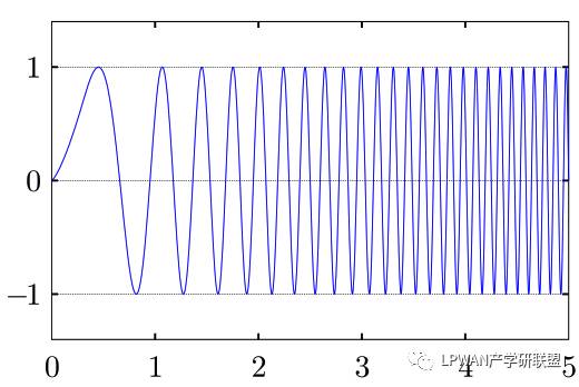
The above image is an example of a linear positive slope:
– Linear frequency modulation spread spectrum technology can greatly extend the transmission distance of signals;
– The time bandwidth product is much greater than 1 (B*T > 1);
– Linear frequency modulation spread spectrum technology effectively prevents Doppler frequency shift;
– It can be used for low power, low rate transmission.
LoRa Linear Frequency Modulation:
LoRa linear frequency modulation uses three different bandwidths: 125KHz, 250KHz, and 500KHz (here, 125KHz is used). The LoRa signal is modulated with a positive slope at a bandwidth of 125kHz, utilizing different orthogonal spreading factors based on data rate and channel conditions. LoRa uses spreading factors from SF7 to SF12.
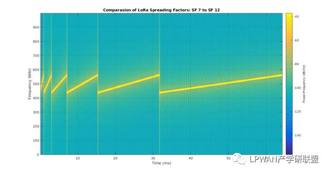
The above image shows the spectrum of different spreading factors: The LoRa physical layer includes 8 preamble symbols, 2 synchronization symbols, physical layer payload, and optional CRC.
– SF8 takes twice the time of SF7, and SF9 takes twice the time of SF8;
– The relationship between symbol rate (Rs), bandwidth (BW), and spreading factor (SF): Rs = BW / (2^SF);
– The higher the spreading factor > the longer the air transmission time;
– The smaller the spreading factor > the higher the data rate.
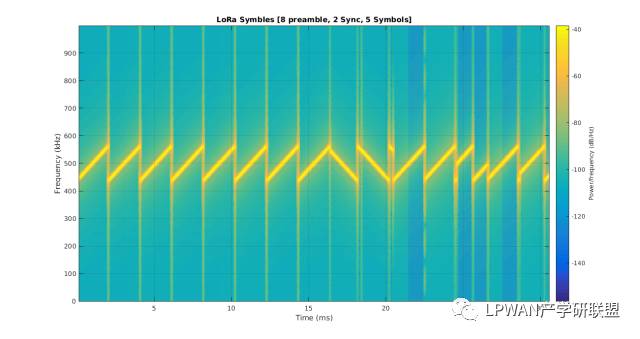
The above image is the spectrum of the LoRa physical layer, where the first eight positive slope signals are used to detect the preamble symbols of LoRa linear modulation, followed by 2 negative slope signals used for time synchronization, and then 5 modulation signals (payload). The frequency jumps represent the modulated signals.