From bulky CRT monitors and plasma TVs to the currently rising laser TVs, the family of display technologies is quite extensive. Many of these display technologies have gradually been replaced over time, but one member has been “shining” since the 1980s: the liquid crystal display (LCD).
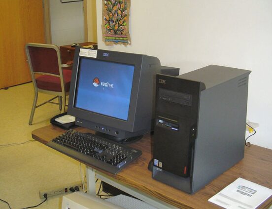
In the 1990s, CRT monitors were prevalent; they were bulky and had a large rear, leaving a deep impression on many. However, they have long been replaced by the more lightweight LCD monitors.
(Image source: Wikipedia)
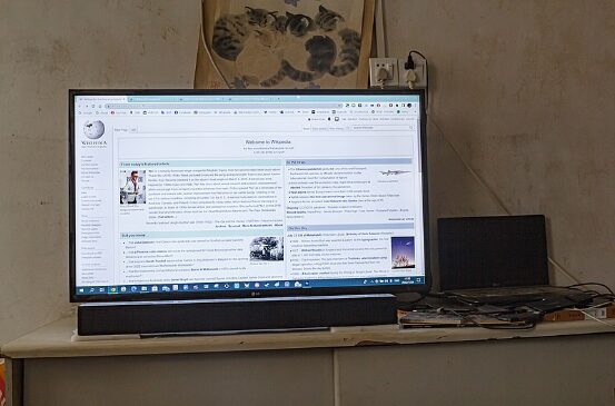
Since replacing CRT monitors, LCDs have been widely used.
(Image source: Wikipedia)
LCDs appeared around the same time as plasma TVs, but they are significantly more well-known and widely used. So what technology does the affordable and user-friendly LCD employ, and what are its characteristics?
Combining Solid and Liquid Properties—The Unique Structure of Liquid Crystals
LCDs are very common in our lives; televisions, computers, and various small household appliances almost all use LCDs. To understand LCDs, we first need to know what “liquid crystal” materials are. The name itself reveals its characteristics: “liquid” signifies a liquid, while “crystal” indicates a solid substance—meaning that liquid crystals possess properties of both solids and liquids.
We know that water exists in three states: solid (ice), liquid (water), and gas (steam), and most substances exhibit these three states as well. Liquid substances are isotropic in molecular distribution, meaning their physical properties are consistent in all directions, a result of random molecular motion. Solids, being crystalline, have an anisotropic molecular distribution, with different arrangements in various directions. This leads to different physical properties, such as refractive index, polarization characteristics, thermal conductivity, and electrical conductivity, in different directions.
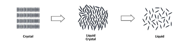
Internal molecular structures of crystal (left), liquid crystal (middle), and liquid (right)
(Image source: Rajak P, Nath L K, Bhuyan B. Liquid crystals: an approach in drug delivery[J]. Indian Journal of Pharmaceutical Sciences, 2019, 81(1): 11-21.)
In the past, people believed that solids and liquids were distinctly separate. However, in 1888, botanist Friedrich Reinitzer extracted a compound known as cholesteryl benzoate from plants, breaking this perception. It has two different melting points, and in a molten state or when dissolved in a solvent, it loses the rigidity of a solid, forming an intermediate state that exhibits partial properties of both crystals and liquids. Due to this unique state, it was named “liquid crystal.” Liquid crystals can be classified into three types based on their anisotropic arrangement: nematic, smectic, and cholesteric.
Nematic liquid crystal molecules are elongated and can flow under external forces, aligning their long axes along the flow direction, generally oriented in the same direction and able to pass through each other.
In smectic phases, liquid crystal molecules are layered. The long axes of the molecules within each layer are parallel and perpendicular to the layer plane. However, the positions of the molecules are not orderly, leading to a state known as positional disorder with directional order. Smectic liquid crystal molecules can only move within their layer, while layers can slide past one another.
Cholesteric liquid crystal molecules are also layered, with each layer having a directional order. However, overall, the layers are stacked in a helical pattern, with each layer rotated at a slight angle relative to the layers above and below.
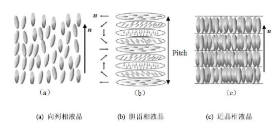
Types of liquid crystal arrangements: nematic, smectic, and cholesteric
(Image source: Zheng Guili. Study on the flexoelectric effect and flexoelectric coefficient of nematic liquid crystal[D]. Changchun Institute of Optics, Fine Mechanics and Physics, Chinese Academy of Sciences, 2017.)
Structure Determines Properties—Various Effects of Liquid Crystals
The fascinating ordered arrangement of liquid crystal molecules also imparts different properties, such as twisted nematic effect (TN).
Nematic liquid crystal materials are sandwiched between two glass substrates, much like a sandwich. The glass surfaces have very fine parallel grooves, known as alignment films. The liquid crystals near the upper glass align according to the direction of the grooves on the upper alignment film, while those near the lower glass align according to the direction of the grooves on the lower alignment film. If the two grooves are crossed, the liquid crystals between the upper and lower glass will twist uniformly. From a top view, the upper layer of liquid crystal molecules is arranged laterally while the lower layer is arranged longitudinally, creating a helical twist that can affect the polarization direction of light.
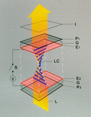
Diagram of the twisted nematic effect
(Image source: Wikipedia)
So what is polarization? We know that light is a type of electromagnetic wave, which can be categorized into two types: transverse waves and longitudinal waves. If one end of a rope is fixed and the other end is pulled taut and vibrated up and down, the motion of the rope you observe is a transverse wave. The characteristic of a transverse wave is that the direction of particle vibration is perpendicular to the direction of wave propagation; electromagnetic waves are typical transverse waves. Longitudinal waves have particle vibration directions parallel to the direction of propagation, and seismic waves are longitudinal waves.
Diagram of a transverse wave; the water waves we typically see are transverse waves, which oscillate up and down, but the direction of wave propagation is perpendicular to the up-and-down movement
(Image source: Wikipedia)
Diagram of a longitudinal wave, also known as a density wave or compressional wave, where the direction of propagation aligns with the direction of vibration, and the wave propagates through changes in density.
(Image source: Wikipedia)
Light waves are transverse waves composed of mutually perpendicular electric fields (z-direction) and magnetic fields (x-direction), with the vibration direction of light always in the x-z plane, perpendicular to the direction of light propagation (y-direction).
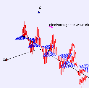
Diagram of light wave propagation, where E represents the electric field, and B represents the magnetic field
(Image source: Wikipedia)
These two different direction vibration vectors combine, and from the x-z plane, it appears as a point mass performing regular motion, which can exhibit circular, elliptical, or linear motion based on varying amplitude and phase, referred to as circularly polarized light, elliptically polarized light, and linearly polarized light, respectively.
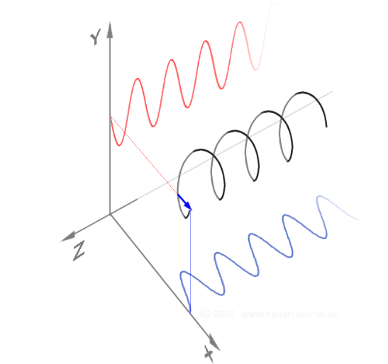
Diagram of circular polarization, where red and blue represent two different vibration directions, and black indicates the actual motion state of the point mass
(Image source: Wikipedia)
If we place a narrow slit, due to the vibration direction of light waves, it will be limited by the slit. If the slit direction aligns with the vibration direction, the wave can pass through smoothly. If the slit direction is perpendicular to the vibration direction, the wave will be blocked and cannot continue propagating. If there is an angle between the slit direction and the vibration direction, the wave can pass through the slit but the light intensity will be weakened. This asymmetry between vibration direction and propagation direction is known as the polarization of light waves; the slit serves as a polarizer.

Diagram of polarization, where the right side shows circular polarization. After passing through the middle slit, the vibration direction aligns with the slit.
(Image source: Wikipedia)
The twisted nematic effect utilizes the property of polarized light to alter the polarization angle of incident light through twisted liquid crystal molecules. So how is this effect applied in LCDs to create images?
In an LCD, there are originally two polarizing filters. These filters only allow polarized light at fixed angles to pass through. When we arrange these two filters at 90° to each other, no light can pass. However, due to the presence of the twisted liquid crystal layer, light from the upper polarizing filter penetrates, twisting 90° as it passes through the liquid crystal molecules, allowing it to exit through the lower polarizing filter, completing the light transmission path.
As we gradually apply voltage to the liquid crystal layer, the liquid crystal molecules will gradually align vertically with the changing voltage, causing the transmitted light to weaken. When the voltage reaches its maximum, the liquid crystal molecules become vertical, and no light can pass through the lower polarizing filter.
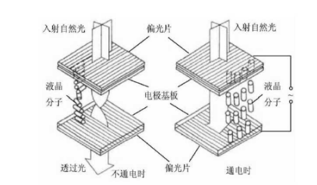
Diagram of TN display technology principle
(Image source: Fang Zeguang. Research on in-plane switching (IPS) thin film transistor (TFT) liquid crystal materials[D]. Beijing University of Chemical Technology, 2015.)
Having understood how the liquid crystal layer transmits light, let’s look at its imaging process. The liquid crystal layer actually contains very small unit cell structures, with each or multiple unit cells forming a pixel on the screen. By controlling the light intensity of different pixels via circuits, a monochrome image is formed.
Color LCDs operate on a similar principle to monochrome displays, except that each pixel consists of three liquid crystal unit cells, each with red, green, and blue filters in front. The light, after being processed by the filters, combines colors using spatial mixing methods to create a rich array of colors.
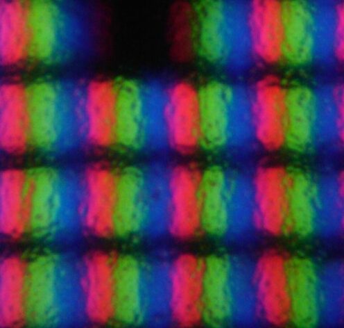
Microscopic structure of TN LCD; each pixel consists of red, blue, and green unit cells.
(Image source: Wikipedia)
This type of liquid crystal screen based on the twisted nematic effect (TN) is what we now refer to as TN screens, which are considered classic technology in LCDs. Its advantage is its short response time, but it also has drawbacks. TN screens have lower contrast, poorer color reproduction, and narrow viewing angles, providing the best viewing experience only when viewed straight on. Due to the inadequate user experience, TN screens are gradually exiting the mainstream market.
People have optimized TN screens based on different liquid crystal arrangements, inventing VA screens (Vertical Alignment) and IPS screens (In-Plane Switching).
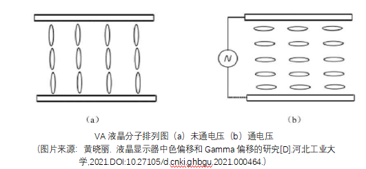
VA screens do not use the twisted nematic effect to present liquid crystals in a helical shape but rather arrange the liquid crystal molecules vertically.
Initially, the liquid crystal molecules are arranged vertically to the upper and lower substrates, with mutually orthogonal polarizers attached to both sides of the liquid crystal box. Without voltage, the linearly polarized light passing through the lower polarizer is parallel to the long axis of the liquid crystal molecules, and the polarization state does not change, preventing it from passing through the upper polarizer, resulting in a dark state. When voltage is applied, the liquid crystal molecules rotate under the electric field, and ultimately the long axis of the liquid crystal molecules aligns with the vertical direction of the electric field, causing the linearly polarized light passing through the lower polarizer to experience phase delay, changing the light’s polarization state until the linear polarized light undergoes a 90° rotation in the liquid crystal layer, aligning the polarization direction with the light transmission axis of the upper polarizer, resulting in a bright state.
Due to the vertical arrangement of liquid crystal molecules in VA screens, when subjected to external forces, the screen exhibits significant deformation, forming patterns similar to water ripples, hence it is also referred to as a soft screen. VA screens have a larger viewing angle compared to TN screens, but the larger rotation angle leads to longer response times, resulting in noticeable ghosting.
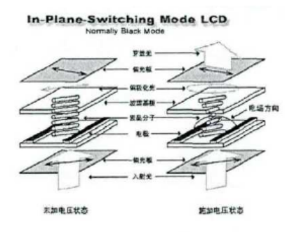
The principle of IPS display technology is illustrated in the following diagram, where electrodes are distributed on one side of the lower substrate, and liquid crystal molecules are arranged parallel to the substrate and at a certain angle to the electrodes. Polarizers are attached to both sides of the liquid crystal box. Without voltage, the linearly polarized light passing through the lower polarizer is parallel to the liquid crystal molecules’ long axis, and the polarization state does not change, preventing it from passing through the upper polarizer, resulting in a dark state. When voltage is applied, the liquid crystal molecules rotate in the plane, and the long axis of the liquid crystal molecules becomes orthogonal to the polarization direction of the linearly polarized light passing through the lower polarizer, causing birefringence in the liquid crystal layer, changing the light’s polarization state until the linear polarized light undergoes a 90° rotation within the liquid crystal layer, aligning its polarization direction with the light transmission direction of the upper polarizer, resulting in a bright state.
IPS imaging principle diagram
(Image source: Li Zhifu. Research on TFT-LCD Wide Viewing Angle Technology[D]. Fudan University, 2011.)
Compared to VA screens, IPS screens have horizontally arranged liquid crystal molecules, allowing them to withstand greater pressure without affecting image rendering, hence IPS screens are also known as hard screens.
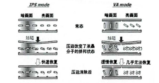
States of liquid crystal molecules in IPS and VA screens under pressure
(Image source: Li Zhifu. Research on TFT-LCD Wide Viewing Angle Technology[D]. Fudan University, 2011.)
Due to the rotation of liquid crystal molecules in the process of transitioning from dark to bright states, they rotate in a plane parallel to the substrates, so from various angles of the liquid crystal panel, the display effect is relatively consistent. Thus, IPS screens can resolve the limited viewing angle issue of TN screens, providing a wider viewing angle for users.
Non-self-lighting—The Source of Light for LCDs
You may have noticed a problem: where does the light source for liquid crystals come from? Indeed, liquid crystals are not self-emitting displays; they require an external light source to illuminate.
The light source for LCDs mainly comes from two types: one is long fluorescent tubes similar to those used for classroom lighting, typically distributed on the sides or bottom of the display. The other is the currently widely used light-emitting diode (LED) light source, where the so-called LED LCDs originate. Since LEDs are very small, using them as a light source allows for thinner displays.
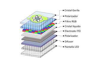
Structure of LED screens (from bottom to top: LED backlight layer, scattering sheet, polarizer, ITO substrate, liquid crystal layer, RGB filter, polarizer, glass layer)
(Image source: Wikipedia)
Conclusion
In fact, LED-based LCDs are not without limitations; their color performance is not particularly outstanding. However, due to their relatively low price and low modulation voltage, they have remained active in our lives since their inception in the 1980s. It can be said that LCDs are truly evergreen members of the display family!
Content source: Science Popularization China APP