For beginners in PLC programming, the key to getting started quickly is toprogress from “hardware recognition” to “simple logic” and then to “practical verification”, step by step, avoiding getting bogged down in complex theories at the beginning. Here is a proven efficient learning path and methods:
1. Define Your Goals: First Understand “What PLC Can Do”
Beginners must first be clear: PLC is an “industrial computer” whose core function is toreceive input signals (such as buttons, sensors) → perform logical operations → control output devices (such as motors, indicator lights).Typical application scenarios include:
- Simple control: light switches, motor start/stop, conveyor belt start/stop;
- Complex control: sequential actions on production lines, machining processes, elevator operation logic.
Start with “simple control”, such as “using a button to control the on/off of a light”; the smaller the goal, the easier it is to gain a sense of achievement.
2. Choose the Right Tools: Start with “Entry-Level PLCs”
Beginners do not need to start with high-end PLCs (such as Siemens 1200/1500, Rockwell); two recommended models arewell-documented, user-friendly software, and low cost entry-level options:
-
Siemens S7-200 SMART:
- Advantages: Comprehensive Chinese manuals, simple and intuitive programming software (STEP 7-Micro/WIN SMART), supports simulation, and second-hand market devices are inexpensive (can be acquired for a few hundred yuan).
- Suitable for: Users who want to systematically learn structured programming and will later work with Siemens series.
Mitsubishi FX3U/FX5U (or simplified version FX3GA):
- Advantages: Ladder diagram programming is closer to traditional relay logic, widely used in the Asian market, and has abundant tutorial resources.
- Suitable for: Users who prefer Japanese brands or will work with small equipment control in the future.
Software Preparation: Download the corresponding programming software directly from the official website (both Siemens and Mitsubishi offer free downloads), and familiarize yourself with the interface (programming area, instruction library, device monitoring area) after installation.
3. Hardware Recognition: Understand “Input and Output” in 30 Minutes
The core of PLC programming is “input → logic → output”; understanding hardware connections first will make learning programming easier:
-
Input (I): Interfaces that receive external signals, such as:
- Buttons (normally open / normally closed), limit switches, proximity switches, photoelectric sensors, etc.
- Wiring principle: When the input signal is activated, the corresponding “input relay” (e.g., I0.0) is “1” (ON), otherwise it is “0” (OFF).
Output (Q): Interfaces that control external devices, such as:
- Indicator lights, contactor coils, solenoids, small motors, etc.
- Wiring principle: When the output relay (e.g., Q0.0) is “1”, the corresponding interface is activated, driving the device to operate.
Simple Wiring Exercise: Find a button (input) and an indicator light (output), and wire them according to the manual:
- One end of the button connects to the PLC input point (e.g., I0.0), and the other end connects to 24V+; the PLC input common terminal (1M) connects to 24V-.
- One end of the indicator light connects to the PLC output point (e.g., Q0.0), and the other end connects to 24V+; the PLC output common terminal (2M) connects to 24V-. (Note: Connect wiring with power off; use the PLC’s built-in or external switching power supply for the 24V power supply to avoid damaging the equipment!)
4. Getting Started with Programming: Learn from “Ladder Diagrams” and Master 3 Core Logics
PLC programming languages include ladder diagrams (LD), instruction lists (STL), SCL (structured text), etc.;ladder diagrams resemble electrical schematics and are the first choice for beginners. Mastering 3 basic logics will allow you to achieve 80% of simple control:
1. Basic Logic: “Momentary Control” (Pressing the button once turns the light on; releasing it turns the light off)
Control Requirements: Press button I0.0, indicator light Q0.0 turns on; release the button, the light turns off.Ladder Diagram Logic:
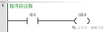
Interpretation: I0.0 is a normally open contact (the button is open when not pressed), and when pressed, it closes, energizing the Q0.0 coil (light on); when released, I0.0 opens, de-energizing Q0.0 (light off).
- Practical Exercise: Draw the ladder diagram in the software, download it to the PLC (or use simulation software), press the button to test, and observe the state of the light.
2. Core Logic: “Self-Latching Control” (Pressing the button once starts it, pressing it again stops it)
Control Requirements: Press the start button I0.0, Q0.0 turns on and stays on (it does not turn off when released); pressing the stop button I0.1 turns Q0.0 off.Ladder Diagram Logic:
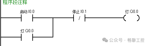
Interpretation: To start, press I0.0, Q0.0 is energized, and at the same time, the normally open contact of Q0.0 closes (self-latching); after releasing I0.0, the current continues to flow through the self-latching contact, keeping Q0.0 energized.
- To stop: Press I0.1 (the normally closed contact opens), cutting off the circuit, Q0.0 loses power, and the self-latching contact opens.
- Why it Matters: This is the fundamental logic for the “continuous operation” of motors and devices, and it must be thoroughly understood!
3. Safety Logic: “Interlocking Control” (Preventing conflicting actions, such as forward and reverse motor operation)
Control Requirements: The forward button I0.0 controls Q0.0 (forward contactor), and the reverse button I0.1 controls Q0.1 (reverse contactor); both cannot operate simultaneously.Ladder Diagram Logic:
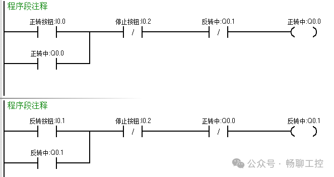
Interpretation: The forward circuit is in series with the normally closed contact of the reverse output Q0.1, and the reverse circuit is in series with the normally closed contact of the forward output Q0.0. This way, when Q0.0 is energized, the normally closed contact of Q0.1 opens, ensuring that the reverse cannot start, and vice versa.
- Significance: Preventing equipment conflicts (such as short circuits from forward and reverse motor operation) in industry is the core of safety control.
5. Utilizing Tools: Use “Simulation Software” to Quickly Verify Logic
Beginners can learn even without hardware! Both entry-level PLCs have simulation tools:
- Siemens: STEP 7-Micro/WIN SMART comes with “PLCSIM”, which can simulate input signals (click I0.0 to simulate button press) and observe output status (whether Q0.0 lights up).
- Mitsubishi: GX Works2 with “GX Simulator”, which has similar functionality.
Simulation Steps: Draw the ladder diagram → click “Simulation Start” → manually trigger inputs (e.g., force I0.0 to ON) → observe whether output Q acts according to logic. Simulation can quickly verify logical errors, making it 10 times more efficient than connecting hardware.
6. Advanced Path: From “Instructions” to “Small Projects”
After mastering basic logic, progress in the following order, consolidating each stage with 1-2 small projects:
-
Learn Common Instructions:
- Timers (TON: delay on, TOF: delay off): for example, “the light turns on 3 seconds after pressing the button”.
- Counters (CTU: count up): for example, “alarm after counting to 5”. (Test each instruction with simulation to understand “set value”, “current value”, and “reset conditions”)
Do Small Projects:
- Stage 1: Traffic light control (red light on for 3 seconds → yellow light on for 1 second → green light on for 3 seconds, repeating).
- Stage 2: Conveyor belt control (after starting, the conveyor runs; when an object reaches the end (detected by a photoelectric sensor), the conveyor stops for 3 seconds before restarting).
- Stage 3: Simple robotic arm (up/down/left/right movement, using limit switches for position detection).
Read Manuals + Copy Programs: Find official example programs (such as the “S7-200 SMART Example Library” on the Siemens website), understand them, copy them, and then modify parameters (such as timer times) to observe changes. Imitation is a shortcut to quickly mastering programming thinking.
7. Pitfall Guide: 3 Common Mistakes Beginners Make
-
Only Learn Software, Avoid Hardware: Programming ultimately controls actual devices; common issues include wiring errors (such as reversing power supply polarity) and incorrect input signal types (such as NPN/PNP sensors). Always practice wiring, even if it’s just connecting one button and one light.
-
Logic Not Closed Loop, Ignoring “Stop Conditions”: For example, when writing self-latching control, forgetting to add a stop button can lead to the device starting and not being able to turn off. When programming, first think about “how to start”, then think about “how to stop”, ensuring every action has a beginning and an end.
-
Pursuing Complexity, Skipping Basics: Do not start by learning “interrupts”, “high-speed counting”, or “PID”; first practice “self-latching, interlocking, timers, and counters” until you can draw the ladder diagram with your eyes closed, then advance later.
Conclusion
The core of PLC programming is “logical thinking + practical verification”. Beginners can achieve simple control in 1-2 weeks and independently complete medium-sized device program design in 1-2 months by following the path of “hardware wiring → basic logic (self-latching / interlocking) → simulation testing → small project practice”. The key is:to read less theory, draw more ladder diagrams, connect more actual circuits, and when encountering problems, first check the manual, then ask in forums (such as Industrial Control Network, Siemens Forum).