
Source: Web
Authors: Chen Manshan, Yuan Yang
The medical ultrasound diagnostic equipment refers to devices that utilize the properties of ultrasound to perform examination functions. Ultrasound is a mechanical wave with a vibration frequency >20kHz, which exceeds the upper limit of human hearing. The frequency range of ultrasound is from 2×10⁻² to 2×100 Hz, while the frequency range of medical ultrasound is between 200kHz and 40MHz, with commonly used frequencies in ultrasound diagnosis ranging from 1 to 10MHz. The high frequency and short wavelength of ultrasound give it characteristics such as directionality, refraction, and reflection [1].
Medical ultrasound diagnostic equipment mainly consists of two parts: the main device and the ultrasound probe. The ultrasound probe is a key component of the ultrasound imaging equipment, responsible for converting electrical signals into ultrasound signals or vice versa. The main unit of the ultrasound diagnostic equipment primarily processes and displays the signals received from the probe [2].
01
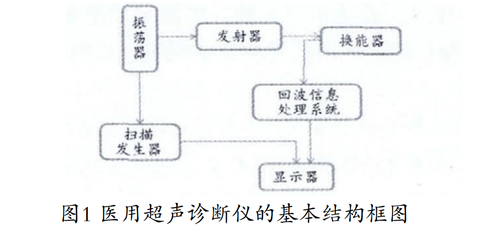
Basic Structural Block Diagram of Medical Ultrasound Diagnostic Equipment
02
Working Principle of Medical Ultrasound Diagnostic Equipment
The oscillator is a synchronous trigger signal generator that produces synchronous trigger pulses to control the operation of the system, determining the repetition frequency of the emitted pulses. After triggering, the transmitter generates high-voltage electrical pulses to excite the ultrasound transducer to emit ultrasound pulses towards the target. The echo pulse signals formed by the target are received by the transducer and converted into electrical signals, which then enter the echo information processing system. This system consists of a radio frequency signal receiving amplifier, a detector, and a video amplifier, and is ultimately displayed on a monitor. The scanning generator outputs scanning signals to the monitor under the control of the synchronous pulses generated by the oscillator, ensuring the ultrasound echo images are displayed stably [3-4].
03
Main Unit of Medical Ultrasound Diagnostic Equipment
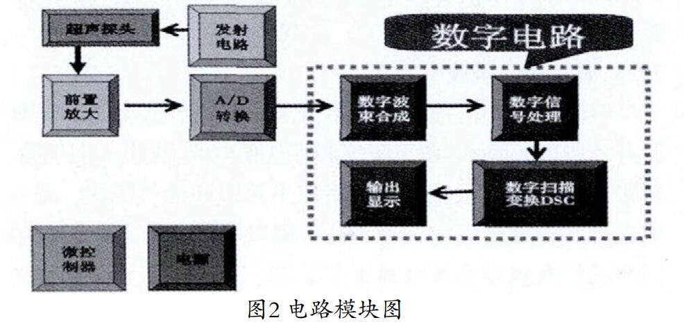
With the advancement of electronic technology, the internal circuits of ultrasound diagnostic equipment have gradually transitioned from analog circuits to digital synthesis circuits, resulting in the fully digital ultrasound diagnostic devices we have today. The specific circuit modules are shown in Figure 2, which mainly include the preamplifier circuit, A/D conversion circuit, digital circuit, and power supply section. The ultrasound probe transmits the received signals to the preamplifier circuit for amplification, converts the analog signals into digital signals through the A/D conversion circuit, and then processes them through the digital circuit. After digital scanning transformation (DSC), the processed images are displayed on the monitor. The power supply section provides power to all the above components.
04
Structure and Principle of the Ultrasound Probe
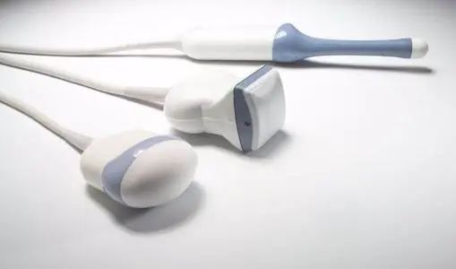
The ultrasound probe can emit and receive ultrasound, performing the conversion of electrical-acoustic signals. It converts the electrical signals sent from the main unit into high-frequency oscillating ultrasound signals and can also convert the ultrasound signals reflected back from tissues and organs into electrical signals displayed on the main unit’s monitor.
The probe generates ultrasonic waves through the piezoelectric chip inside it, which produces elastic deformation when powered on, thus generating ultrasound waves. Conversely, when ultrasound waves pass through the chip, they can cause elastic deformation, leading to a change in voltage, which is processed by the signal processing board to complete the imaging of the detected object. This processing is known as the piezoelectric effect. The piezoelectric effect refers to the reversible acoustic-electric characteristic of crystals situated in elastic media.
Currently, commonly used piezoelectric materials for ultrasound probes include lead zirconate, barium titanate, quartz, and lithium sulfate, among others. Barium titanate and lead zirconate are polycrystalline ceramics sintered at high temperatures. After sintering the green body into a ceramic body, it is appropriately ground and adjusted to obtain the desired geometric dimensions, and then polarized using a high-voltage direct current field to exhibit piezoelectric properties, becoming a transducer device. The more commonly used ultrasound probes today include convex array probes, linear array probes, cavity probes, and high-frequency linear array probes.
The ultrasound probe is one of the important components of ultrasound diagnostic equipment. In its structural composition, the piezoelectric chip, matching layer, and absorption block are significant parts.
The piezoelectric chip is the most crucial part of the probe, used to receive electrical pulses to generate mechanical ultrasound vibrations, completing the acoustic-electric and electric-acoustic conversion tasks.
The matching layer is situated between the acoustic lens and the piezoelectric array. Since the acoustic lens contacts both the crystal transducer and the human body, the impedance difference between the two is significant, making it difficult to match the characteristic impedance of the acoustic lens with both. Ultrasound propagating across interfaces with different impedances will produce reflections, increasing energy loss and affecting resolution; therefore, a matching layer is often required to achieve impedance matching between the probe and the load. In addition to the requirements for thickness and acoustic impedance, the matching layer should have low acoustic damping to minimize energy loss.
The absorption block, also known as the damping block, is used to attenuate and absorb the ultrasound energy radiated backward by the piezoelectric transducer, preventing it from reflecting back and prolonging the ringing time of the transducer. Therefore, the damping material should have a high attenuation capacity and an acoustic impedance close to that of the piezoelectric material, ensuring that all sound waves radiated backward from the piezoelectric transducer enter the damping material and do not reflect back to the transducer.
[References]
[1] Shi Mingguo. Medical Imaging Equipment [M]. Beijing: Higher Education Press, 2008.
[2] Zhu Hongfeng, Mao Dawei, Li Jun. Analysis and Repair of GELCVPLUS Digital Subtraction X-ray Machine with No Image Display] Chinese Medical Equipment, 2011, 26(1): 124-125.
[3] Lei Ruiqiang, Zheng Guofang. Analysis of Typical Faults in Magnetic Resonance Water Cooling Machine]. Practical Medical Technology Journal, 2008, 15(26): 3555.
[4] Qin Weichang. Medical Imaging Equipment [M]. Beijing: People’s Military Medical Press, 2006.
Statement
1. This article is a reposted article, intended for sharing and not for any commercial use. Copyright belongs to the original author.
2. Some articles cannot confirm the original author due to many reposts, and only the source of reposting is indicated. If there is any infringement, please contact us promptly, and we will delete it immediately and apologize. Thank you!
Past Highlights
Repair Case: Philips IU22 Ultrasound Equipment No Display
Repair Case: Philips IU22 Ultrasound Cannot Power On
Repair Case: Philips IU22 Ultrasound Alarm Reset