112023 Good News
© dream18560710



INVITATION
Embedded Systems
Design Teaching

Design of Embedded Intelligent Car Based on RTT-Thread

Intelligent Car Practical Education Base
Design of Embedded Intelligent Car Based on RTT-Thread
Instructor:Gou Jun Nian


Practical Design Instructions

As part of the process assessment for the “Embedded System Design” course, the hands-on practical section involves designing and implementing an intelligent car based on RT-Thread, with the following specific requirements:
1. This section is a mandatory part of the process assessment, accounting for 20% of the total score;
2. This section is to be completed in groups (grouping organized by the instructor), with scores assessed by group;
3. The physical production of the car and a scenario-based operational demonstration are required;
4. Groups must complete design, integration, debugging, analysis, and summary report defense (the report must be in video format, lasting no less than 15 minutes);
5. Specific requirements will be adjusted and explained by the relevant instructors.

1.2 Practical Operation Steps
As part of the process assessment for the “Embedded System Design” course, the hands-on practical section involves designing and implementing an intelligent car based on RT-Thread, with the following specific requirements:
1. This section is a mandatory part of the process assessment, accounting for 20% of the total score;
2. This section is to be completed in groups (grouping organized by the instructor), with scores assessed by group;
3. The physical production of the car and a scenario-based operational demonstration are required;
4. Groups must complete design, integration, debugging, analysis, and summary report defense (the report must be in video format, lasting no less than 15 minutes);
5. Specific requirements will be adjusted and explained by the relevant instructors.

Design Scheme and Principles

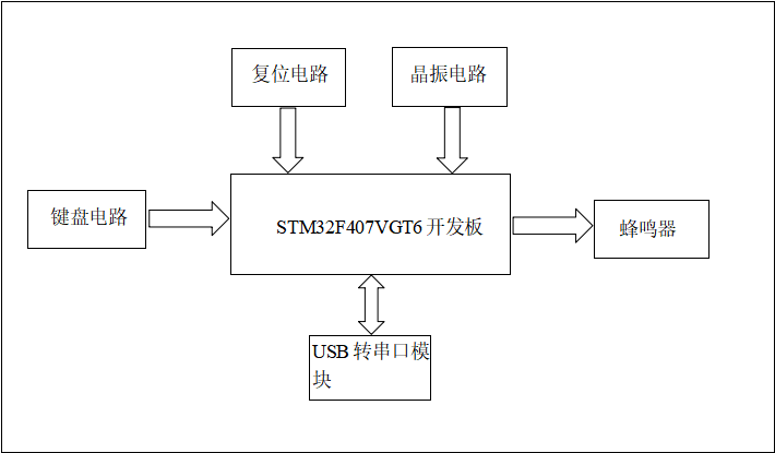
Using the STM32F407VGT6 development board as the core, combined with a matrix keyboard (4×4), a buzzer, and a USB to serial module (CH340), a multi-threaded communication mechanism verification system is constructed. The main thread periodically scans the keyboard row and column signals (PA0-PA7) to detect key events, passing commands to the control thread via a mailbox, which drives the PB0 pin to output PWM signals to control the buzzer’s tone and sound; the debugging thread outputs logs to the PC in real-time via UART1 (PA9/PA10). The experiment is based on the RT-Thread kernel to implement thread priority scheduling, combined with semaphores to ensure safe resource access, verifying the feasibility of multi-thread collaboration, asynchronous communication (mailbox/queue), and real-time performance (millisecond-level response), as shown in the overall design block diagram:

Hardware Design


3.1 Hardware Selection
(1) Microcontroller: The STM32F407VGT6 microcontroller chip is used, featuring a 32-bit ARM Cortex-M4 processor core, with single-cycle MAC instructions, and built-in flash memory of up to 1MB and 192KB of SRAM. It supports various communication interfaces such as USB OTG FS, CAN, I2C, SPI, USART, etc., allowing easy connection to various peripheral devices. Additionally, this microcontroller provides rich analog and digital peripheral functions, such as ADC, DAC, timers, PWM, and GPIO, providing strong support for implementing complex functions.
(2) Matrix Keyboard Module: The matrix keyboard is a common input device in embedded systems, achieving efficient input through a row-column scanning mechanism. This experiment uses a 4×4 matrix layout, containing 16 keys, supporting numeric, alphabetic, and functional command inputs. In hardware, the row lines (ROW) are connected to the GPIO output pins (PA0-PA3) of the STM32, and the column lines (COL) are connected to the input pins (PA4-PA7). During operation, the system outputs a low level row by row and detects changes in the column line levels to identify the key position, combined with interrupt triggering (triggering GPIO interrupt when a key is pressed) and software debounce algorithms to avoid false triggering due to mechanical bounce. In the communication mechanism experiment, the matrix keyboard serves as the core input device, passing key commands to the control thread through inter-thread communication (mailbox or message queue), enabling functions such as starting/stopping the buzzer and switching motor directions, making it a key module for human-computer interaction.
(3) Buzzer Module: The buzzer is a device that converts electrical signals into sound signals. In this experiment, an active buzzer is used, with the sound frequency controlled by PWM signals. In terms of hardware connection, the buzzer’s negative terminal is grounded, and the positive terminal is connected to the GPIO output pin (PB0) through a current-limiting resistor. By adjusting the PWM duty cycle, the tone can be changed (high duty cycle corresponds to high pitch, low duty cycle corresponds to low pitch), and on/off control is used to achieve sound on/off. In the experiment, the buzzer serves as a feedback module, triggering a thread to send control commands when the user presses a specific key (KEY1), causing the GPIO to output a high level to drive the buzzer to sound. A short press triggers a single beep (confirming the operation), while a long press triggers a continuous sound (alarm prompt). Thread control achieves real-time feedback of sound effects to user operations, verifying the reliability of the communication mechanism.
(4) USB Serial Module: The USB serial module is the core interface for debugging the embedded system with the PC. In this experiment, the CH340G or FT232RL chip is used to implement communication between the STM32’s USART1 (PA9/TX, PA10/RX) and the PC’s USB. In hardware connection, the STM32’s TX pin is connected to the module’s RX, the RX pin is connected to the module’s TX, and GND is common ground. The module supports automatic baud rate adaptation (115200bps) and communicates with the PC via a USB virtual COM port. In the experiment, the serial module is used to output debugging information (key status, thread running logs), transmitting data in real-time to the PC terminal via the printf function. Its plug-and-play feature simplifies the development process and is compatible with Windows/Linux systems. In the communication mechanism experiment, the serial output provides developers with an intuitive means of monitoring system status, assisting in verifying thread scheduling and communication protocol (mailbox/queue) correctness, making it an important tool for hardware-software collaborative debugging.

3.2 Communication Mechanism Experiment – Principles
Through the STM32F407VGT6 development board, a multi-threaded communication mechanism verification is implemented, with hardware configuration centered around the matrix keyboard, buzzer, and USB serial module, supplemented by the STM32’s GPIO and UART resources.
1. Features
1. Multi-thread collaboration:
The main thread is responsible for scanning the matrix keyboard and task scheduling, while the child threads independently handle buzzer control and serial communication.
By isolating threads, blocking is avoided, improving system response efficiency.
2. Asynchronous communication mechanism:
Mailbox: Passes key events (e.g., KEY1 triggers the buzzer to sound once).
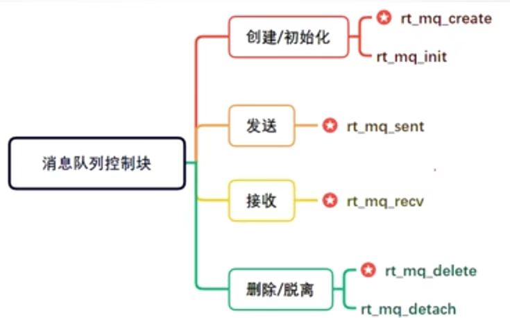
Message queue: Synchronizes buzzer control commands and status feedback.
Semaphore: Protects shared resources (e.g., serial transmission buffer).
3. Hardware abstraction and reuse:
The STM32 simulates the matrix keyboard scanning logic through GPIO, reducing peripheral dependencies.
The buzzer achieves adjustable tone through PWM output, and the serial port directly outputs debugging information.
4. Real-time performance assurance
Based on the RT-Thread kernel, thread priority scheduling ensures controllable communication delays (millisecond-level response).
2. Working Principles
1. Thread interaction process
Key detection thread:
Scans the matrix keyboard (PA0-PA7 row-column scanning) to detect key press events.
Sends key values (e.g., KEY1→1, KEY2→2) to the control thread via a mailbox.
Control thread:
Parses key commands, controls the buzzer (PB0) to start/stop or adjust PWM frequency.
Outputs debugging logs via serial (PA9/PA10).
Debugging thread:
Real-time prints system status via serial.
2. Communication mechanism implementation
Mailbox: Short message passing.
Message queue: Periodically updates data.
Semaphore: Coordinates multi-thread access to shared resources (buzzer).
3. Hardware interface communication
UART debugging output:
Sends logs to the PC terminal via the printf function, with a baud rate set to 115200bps.
GPIO interrupt scanning:
Triggers an interrupt when the matrix keyboard is pressed, combined with debounce algorithms to avoid false triggering.
3. Key Steps
1. Matrix keyboard scanning:
Hardware connection: STM32’s PA0-PA3 configured as GPIO outputs, outputting low levels row by row to scan the matrix keyboard’s row lines (ROW); PA4-PA7 configured as GPIO inputs to detect changes in the column lines (COL).
Software process: Polling the row line status, combined with changes in column line levels to calculate key coordinates, and sending key values to the control thread via a mailbox.
2. Buzzer control:
Hardware connection: The buzzer’s positive terminal is connected to a 3.3V power supply, and the negative terminal is connected to the PB0 pin through a current-limiting resistor.
Software process: After receiving mailbox commands, outputs a high level on PB0 to drive the buzzer to sound, and a low level to mute; uses PWM to adjust the duty cycle to control the tone (e.g., 50% duty cycle corresponds to mid-frequency sound).
3. Serial debugging output:
Hardware connection: STM32’s PA9 (TX) and PA10 (RX) connect to the CH340 USB to serial module, enabling data exchange with the PC.
Software process: Initializes USART1 baud rate to 115200bps, and outputs key status and thread logs to the PC terminal in real-time via the rt_kprintf function.
4. STM32 thread scheduling:
Creates three threads:
Main thread: Periodically scans the matrix keyboard (100ms cycle) to detect key events.
Control thread: Parses key commands and controls buzzer actions (medium priority).
Debugging thread: Asynchronously outputs log information (lowest priority) to avoid interfering with real-time tasks.
4. Advantages
Through STM32 multi-thread scheduling and collaboration with the matrix keyboard, buzzer, and serial, efficient resource utilization and real-time communication verification are achieved. The single-bus keyboard scanning requires only 8 GPIO lines to support 16-key input, and the mailbox/queue ensures zero loss in command transmission; the buzzer’s PWM tone adjustment combined with serial logs forms a “dual feedback” system, with key response delays under 10ms; the RT-Thread kernel ensures thread priority scheduling, with critical tasks responding in milliseconds. The hardware reusability is strong, with single-bus, UART, and other interfaces allowing for quick sensor expansion, low-cost coverage of multi-threading and multi-communication mechanism verification, suitable for real-time scenarios in industrial control and smart homes.

Software Design


4.1 Threads

4.2 Inter-thread Communication Mechanism
-
Mailbox
2. Message Queue

4.3 Function Summary
1. Hardware Configuration:
Using STM32’s PA0 (KEY1) and PA1 (KEY2) to detect key inputs.
Control the buzzer through the PA pin (BEEP_PIN definition needs to be uncommented).
Use mailbox (Mailbox) for inter-thread communication.
2. Thread Division of Labor:
Key scanning thread: Periodically checks key status and sends control commands via mailbox.
Buzzer control thread: Receives commands and controls the buzzer switch (supports string or enumeration commands).
3. Communication Mechanism:
Mailbox (Mailbox): Passes short messages (command values or string pointers).
Conditional Compilation:
Switches message format (string or enumeration) via USE_MB_SEND_STRING macro.
4. Debug Output:
Uses LOG_D to print debugging information, outputting to the terminal via RT-Thread’s debugging log system.
5. Key API Descriptions:
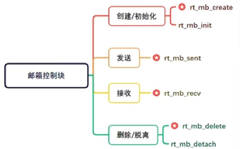
rt_mb_init: Initializes the mailbox, specifying memory pool and scheduling policy.
rt_mb_send: Sends messages to the mailbox (blocking or non-blocking).
rt_mb_recv: Receives messages from the mailbox (blocking wait).
rt_pin_mode/rt_pin_write: Configures and operates GPIO pins.
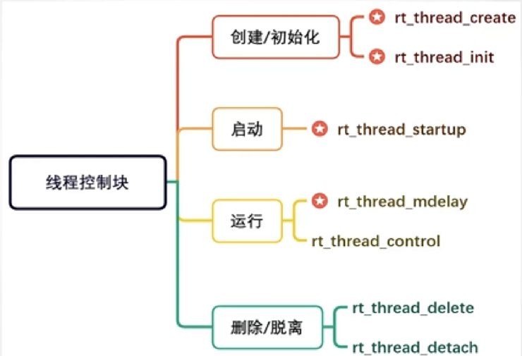
rt_thread_init/rt_thread_startup: Creates and starts threads.

Design Scheme and Principles


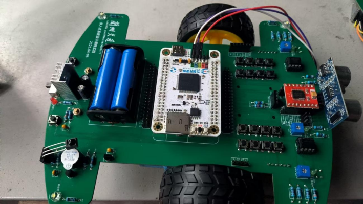
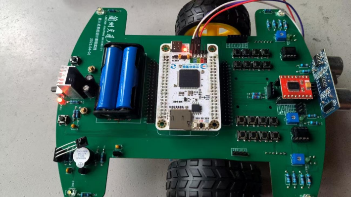
5.1 Physical Debugging Result Images

Conclusion

Through the practice of the intelligent car based on RTT, students learned about the hardware production process of an intelligent car, while through the software part of the communication mechanism experiment, they understood the establishment of threads, mailboxes, and message queues in the RTT development environment, as well as how to communicate between threads using mailboxes and message queues, and how threads collaborate to control the buzzer based on key presses.