(Written by Giacomo Paterniani, Field Application Engineer)
Abstract
This article explores how to implement hardware-independent drivers in projects. The plug-and-play design concept can significantly reduce the complexity of embedded software or firmware design, benefiting designers regardless of their experience level. For an understanding of the basic functions of drivers and the software architecture of embedded systems, please refer to the article “Simplifying Embedded System Design with Hardware-Independent Methods: Basic Knowledge”.
Introduction
In embedded system design, designers often need to write code for drivers and firmware to ensure that the selected sensors can achieve their required basic functions. This process can be time-consuming and tedious. To address this challenge, a plug-and-play design approach can be adopted by integrating hardware, software, and firmware, thereby simplifying sensor selection and system integration. Hardware-independent drivers not only make sensor integration more efficient but also serve as a universal solution that can be reused in future designs. This article will illustrate how to implement hardware-independent drivers using an Inertial Measurement Unit (IMU) sensor as an example, although this method is also applicable to other types of sensors and devices. The drivers are written in C and tested on a general-purpose microcontroller.
Driver Implementation
The appendix contains all the images and code mentioned for readers’ reference.
u adis16500_rd_error_flag
Figure 10 in the appendix shows the implementation of this function. This function reads the error flags contained in the ADIS16500_REG_DIAG_STAT register; if no errors occur, all bits are 0. There are 10 possible errors, so this function returns an ADIS16500_ERROR_FLAGS structure containing 10 boolean fields, each representing an error. The function only reads the ADIS16500_REG_DIAG_STAT register and checks each bit of the register using specific error masks; when a logical 1 is found, the corresponding field in the structure is set to true.
u adis16500_rd_temp
This is a temperature reading function, implemented similarly to the acceleration and gyroscope functions (details can be found in the first article of this series). The read value is expressed in °C. Its binary value is contained in the 16-bit register ADIS16500_REG_TEMP_OUT. The data will then undergo a binary to two’s complement conversion. The resulting two’s complement value will be multiplied by the temperature scale factor (in °C/LSB), ultimately yielding a value in °C, which is recorded in the pointer passed as input. The implementation of this function can be seen in Figure 9 of the appendix.
u adis16500_get_ts_usec
This function is used to obtain the timestamp of the IMU, measured in μs. Its implementation is identical to that of the adis16500_rd_temp function. Specifics can be found in Figure 9 of the appendix.
u adis16500_rd_data_cntr
This program reads the number of data outputs. In fact, it can be achieved simply by reading the register named ADIS16500_REG_DATA_CNTR. When this register reaches its maximum value, it will restart from 0. The implementation of this function can be seen in Figure 9 of the appendix.
u adis16500_wr_acc_calib
This function performs custom offset calibration. Designers can call this function to add the offset value to the values read from the output data register, thereby adding the x, y, z calibration values to the x, y, z acceleration data. The input to this function is a pointer to a structure of type ADIS16500_XL_OUT, which contains x, y, and z float fields. The goal of this function is to convert from float values to binary two’s complement values, and then from binary two’s complement values to binary values. All steps can be seen in Figure 11 of the appendix. Next, the binary values need to be written to the bias registers; for the x-axis, two registers need to be written: ADIS16500_REG_X_ACCEL_BIAS_L (low 16 bits) and ADIS16500_REG_X_ACCEL_BIAS_H (high 16 bits). The same applies to the y and z axes, each having corresponding bias registers. To check if this program executes correctly, when placing the IMU sensor, ensure that the z-axis points vertically towards the sky. In this case, the acceleration values for the x and y axes should be close to 0, while the z-axis acceleration value should be close to -9.81 m/s² (-g). Calling the calibration function and passing a calibration structure where the x, y, and z fields are all equal to -9.81 m/s², the calibrated readings will be x = -9.81; y = -9.81; z = 0, indicating that the calibration offset function is working correctly.
u adis16500_wr_gyro_calib
This is the offset calibration function related to the gyroscope, implemented in the same way as the acceleration calibration function. The difference is that the gyroscope calibration needs to be completed using the corresponding gyroscope offset registers as specified in the datasheet.
This article focuses on the IMU sensor driver, but its software/firmware structure can be used for any type of sensor. Therefore, to achieve universal support for all sensors, adjustments only need to be made according to the communication protocol between the sensor and the microcontroller (such as SPI, I2C, UART, etc.). The initialization method for the sensor remains valid, as the initialization phase records the functions for sending and receiving data via the communication protocol.
How to Introduce and Use Drivers in Projects
In addition to basic explanations about the hardware connections between the sensor and the microcontroller unit (MCU), this article also provides relevant guidelines on how to introduce drivers from the software and firmware perspectives.
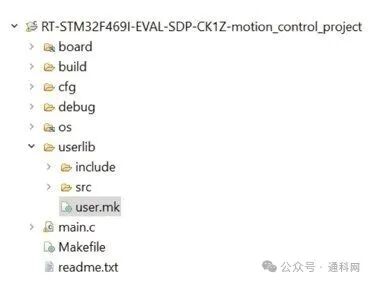
Figure 1. Project folder structure.
There is no universal organization structure for sensor drivers. The suggested folder structure is shown in Figure 1. The userlib folder contains all sensor drivers. In this example, only the IMU sensor driver is included, but if the project contains more sensors, the organization will be essentially the same. The userlib contains two folders: include and src. The include folder contains the header files for the driver, in this case, adis16500.h, while src contains the source files, namely adis16500.c. The userlib also has a makefile specifying the include directive, as shown in Figure 2.
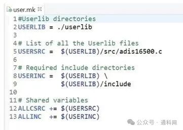
Figure 2. userlib makefile.
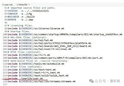
Figure 3. Main makefile.
Figure 3 shows the main makefile. It is located at the application layer, close to main.c. This makefile includes user.mk, as indicated by the red underline in Figure 3 (line 115 of the code).
With the makefile (.mk), designers can introduce the driver interface at the application layer (for example, within main.c) and can call all public functions of the sensor driver. This establishes a link between the application layer and the sensor driver layer. The application layer can access the sensor driver interface (adis16500.h). Therefore, at the application layer, the link between the sensor driver layer and the peripheral driver layer will be established through the initialization program discussed above. In the specific use case of the IMU sensor, the transmitter, receiver SPI functions, and system delay function will be defined in the main.c file, as shown in Figure 2 of the appendix. These three functions fully adhere to the prototypes in the driver header file, as shown at the top of Figure 3 in the appendix. Internally, these three functions are provided by the peripheral driver layer, such as spiSelect, spiSend, spiReceive, spiUnselect, and chThdSleepMicroseconds. Thus, the SPI receiver, transmitter, and system delay functions represent the link between the peripheral driver layer and the sensor driver layer, and these functions will be assigned to the initialization structure, as shown in Figure 2 of the appendix. This is the entire process of introducing drivers into the project.
If designers want to obtain output from the sensor, they can use the functions introduced in the adis16500_rd_acc and adis16500_rd_gyro sections. There is no completely universal method for sensor reading; Figure 4 provides just one example.
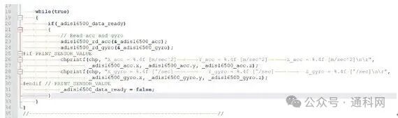
Figure 4. Example of sensor output reading.
In this example, there is an infinite loop in main.c that continuously checks a boolean static variable named _adis16500_data_ready. This variable is associated with a callback function that switches to TRUE when the DR pin goes high, indicating that new data is available. In this case, the main function will call the adis16500_rd_acc and adis16500_rd_gyro functions. By running the IMU sensor at full speed, designers will be able to obtain data at a 2 kHz output data rate (ODR).
Conclusion
This article introduced the functions of drivers and how to simplify sensor integration through hardware-independent methods. Hardware-independent drivers can serve as a universal solution, reusable in future designs.
Author Biography
Giacomo Paterniani holds a degree in Biomedical Engineering from the University of Bologna and a Master’s degree in Electronic Engineering from the University of Modena and Reggio Emilia. After graduation, he worked as a researcher at the University of Modena and Reggio Emilia for a year. In April 2022, he joined ADI’s graduate program as a Field Application Engineer. In April 2023, he became an FAE.