Many friends encounter issues when flashing data on the vehicle, often experiencing disconnections that interrupt the flashing process and result in failure. In such cases, it is necessary to remove the ECU from the vehicle and use manual jumper wiring to perform the flashing. Without further ado, let’s go straight to the steps.
Step 1:
Remove the ECU from under the vehicle.
Step 2:
Locate the required pins according to the ECU model;
Key Point: A total of five wires are needed for ECU flashing.
① Power Positive +
② Power Negative –
③ Ignition Switch T15
④ Flashing CAN +
⑤ Flashing CAN –
Find the corresponding circuit diagram for the ECU (using WISE15 as an example).
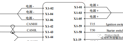
From this part, we can see:
① Power Positive +: The corresponding pin is X1-01/03/05.
② Power Negative -: The corresponding pin is X1-02/04/06.
③ Ignition Switch T15: The corresponding pin is X1-59.
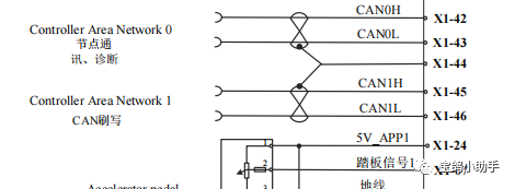
④ Flashing CAN +: Corresponds to X1-45.
⑤ Flashing CAN -: Corresponds to X1-46.
Note: Generally, there are three power supplies on the ECU corresponding to different functions, but they all power the CAN lines, so only one set of power lines + and – needs to be connected.
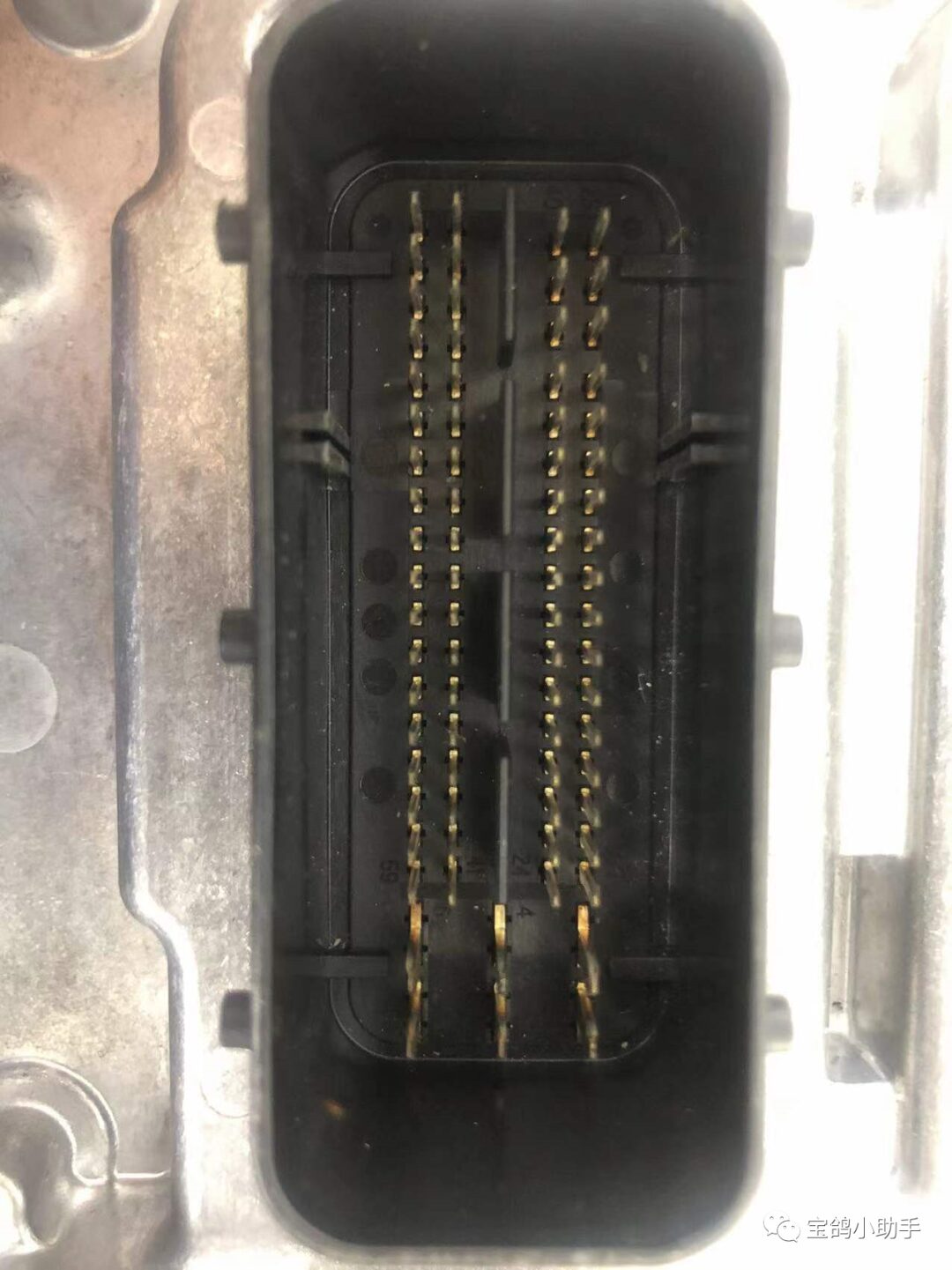
Step 3:
From the removed ECU, locate the corresponding five pins; the ECU will have labels that can be matched.
Step 4:
Prepare the flashing wiring harness. The materials needed are as follows:
① Terminal connectors, used to connect to the ECU pins and the OBD port.
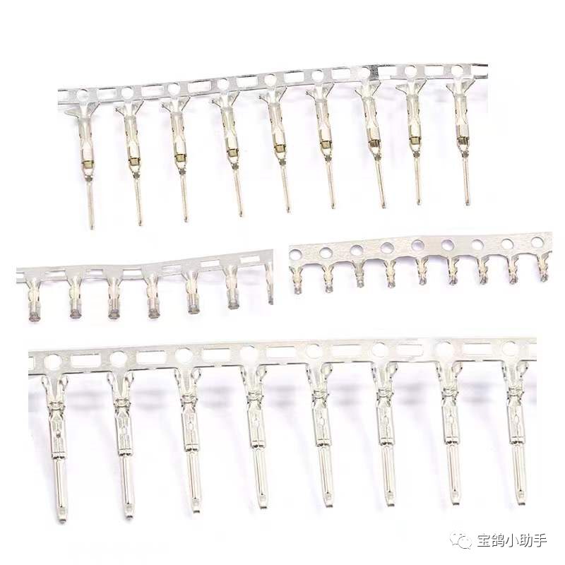
This is the kind of thing.
② Wires, used for connections.
Step 5:
Wiring:
① Flashing CAN + connects to Smart Star 1 pin.
② Flashing CAN – connects to Smart Star 9 pin.
③ Ignition Switch T15 connects to the positive terminal of the battery.
④ Power Positive + connects to the positive terminal of the battery.
⑤ Power Negative – connects to the negative terminal of the battery.
Note: If using the standard version or new generation of Smart Star, two additional wires are needed.
Smart Star 16 pin connects to the positive terminal of the battery.
Smart Star 4 pin connects to the negative terminal of the battery.
Using WISE15 as an example, the specific wiring pins are as follows:
① X1-01 connects to the positive terminal of the battery.
② X1-02 connects to the negative terminal of the battery.
③ X1-59 connects to the positive terminal of the battery.
④ X1-45 connects to Smart Star 1 pin.
⑤ X1-46 connects to Smart Star 9 pin.
For the standard version and new generation of Smart Star, add two more wires:
⑥ Smart Star 16 pin connects to the positive terminal of the battery.
⑦ Smart Star 4 pin connects to the negative terminal of the battery.
Step 6:
The rest is normal software operation.
If after reading the above steps you still do not understand this jumper wiring or do not know which pins to jump, you can scan the QR code to add me on WeChat for consultation.

———————————————————————————————
Money-Saving Tips
Recently, I got some deals on JD appliances, with significant discounts; usually, you can save several hundred on each appliance. Refrigerators, water heaters, gas stoves, TVs, water purifiers, microwaves, washing machines, air conditioners, and dozens of other kitchen and bathroom appliances are available. If you’re interested, you can join the group to take a look; you might save hundreds or even thousands one day, isn’t that great?

If I have disturbed anyone, please forgive me. Thank you all.