Follow 【指尖维修】 for fresh insights on motorcycle maintenance and repair!
Author: 行思止随
Yesterday, we discussed how fuel-injected motorcycles no longer require ignition coils, as their functions have been replaced by the ECU, and we listed the four main functions of the ECU. Today, we will discuss the internal structure and workflow of the ECU.
The ECU contains a storage unit that can comprehensively process the information input from various sensors or other devices and output execution commands. Therefore, it is essentially a microcomputer.
Visually, the ECU includes hardware and software. Hardware refers to the dedicated microcontroller, physical circuits, and input/output interfaces of the fuel injection system ECU. Software refers to the system programs and application programs loaded into the ECU. The system programs of the ECU are divided into two parts: input/output programs and application programs.
All inputs and outputs of the ECU are completed through input/output programs. The workflow is as follows: the signals fed back from the sensors of various subsystems are converted by the input program and provided to the ECU application program, which calculates based on the engine’s operating conditions and the driver’s control signals, and then distributes the results to various system actuators via the output program. What is an actuator, you ask? The spark plug is an actuator; it ignites the mixture based on the high-voltage signal it receives. The fuel injector is also an actuator; it injects fuel into the cylinder based on the pulse width signal to form a mixture.
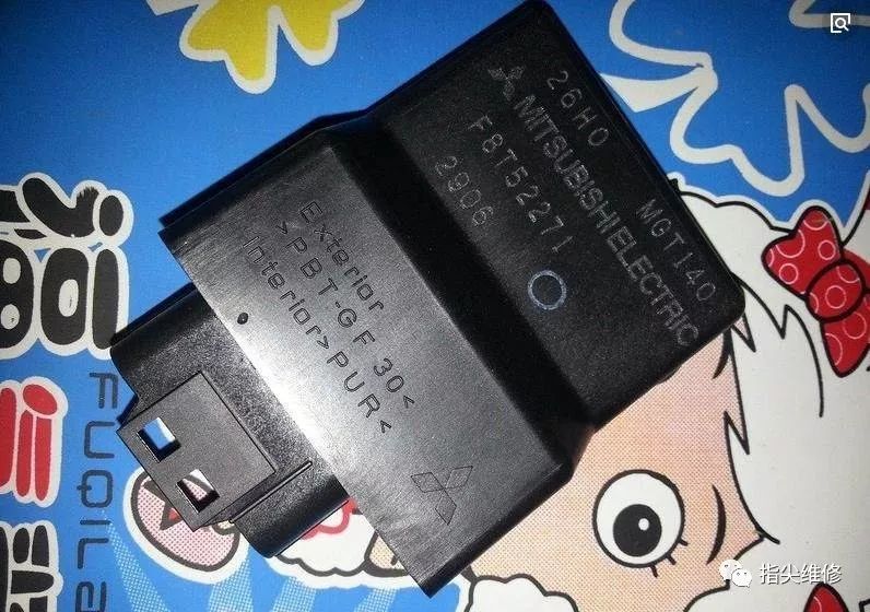
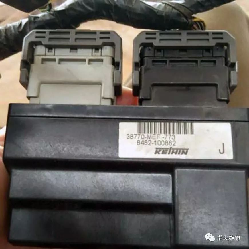
The ECU of fuel-injected motorcycles is usually installed under the motorcycle seat, and some scooters have it installed near the footrest, alongside the battery. Regardless of where it is placed, it is connected to the main power cable through a connector.
The main functions include:
(1) Input rectification and filtering circuit, which receives information input from sensors or other devices and converts it into signals that can be recognized by the microcontroller. For example, if the oxygen sensor detects incomplete combustion, it sends a signal that is provided to the ECU through the input circuit and program.
(2) Providing a 5V reference voltage to sensors. This requires no explanation; it simply provides power to the sensors and actuators.

(3) Communication circuit for writing data to the ECU and error diagnosis interface, which involves storing, calculating, and analyzing various necessary information. This is commonly referred to as fault codes, which assist in the diagnostic system.
(4) Computational analysis to derive output values based on collected signals. The prepared output values are the instructions ready for execution.

(5) Output execution commands, converting weak signals into drive circuit signals for ignition coils, fuel pumps, and injectors. As mentioned earlier, after the sensors provide feedback signals to the ECU, the ECU calculates and then outputs the instructions to the actuators through the output circuit and program. For example, if the oxygen sensor reports a rich mixture signal, the ECU analyzes and calculates it and then instructs the fuel injector to reduce the pulse width, meaning less fuel is injected to make the mixture leaner.