Dynamic Power Path Management for Battery Charging Chips
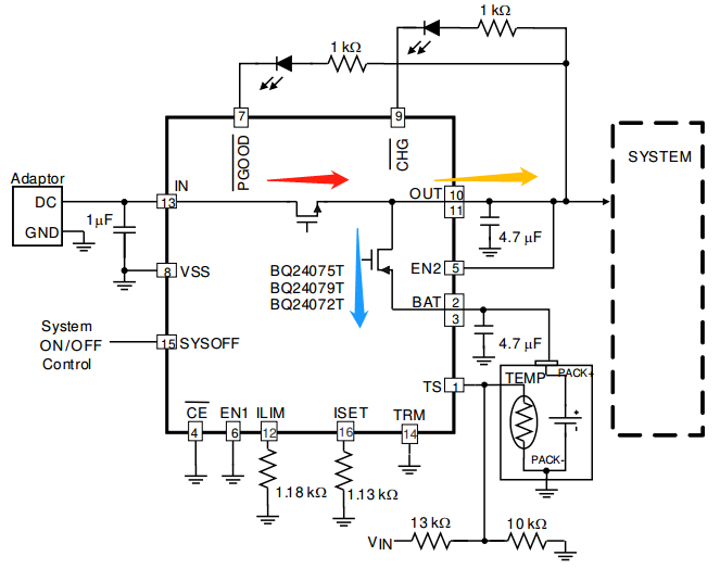
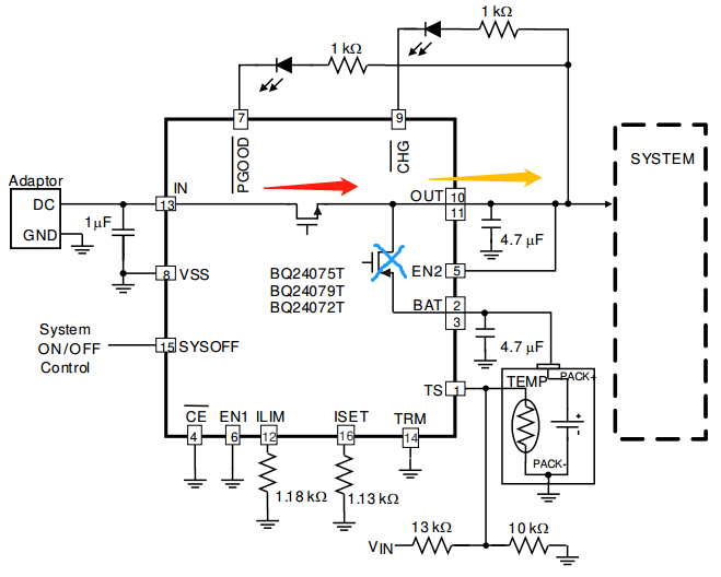
Some battery-powered products, if not designed properly, may exhibit a phenomenon where the battery fails to charge after being over-discharged. The reason is generally that these products lack a dynamic power path management feature in their charging design. When the battery is depleted and charging begins, the product typically activates certain functions to display charging progress to the user. If the system power path and the battery charge/discharge path are not independently separated, the system will draw power from the charging battery. If the battery has a low charge at this time, it could lead to battery failure and stop charging.Moreover, this lack of independent system power paths can lead to excessive charge/discharge cycles, accelerating aging. Charging chips that feature dynamic power path management can perfectly resolve these two issues, allowing the product to start normally as soon as an external power source is connected. This article will briefly introduce the principle of Dynamic Power Path Management (DPPM). For a deeper understanding, one can refer to the datasheets of relevant charging chips.When an external power source is connected, the DPPM circuit begins to continuously monitor the input current and limits the input current to below a certain threshold. The output voltage of the chip is used to power the system load and is adjusted to be 210mV higher than the battery voltage. When the battery voltage drops below 3.2V, the output voltage is fixed at 3.41V. This ensures that even when the battery is completely discharged, the system can still start normally when an external power source is connected. The current coming from the external power source charges the battery while also powering the system, as shown in Figure 1.
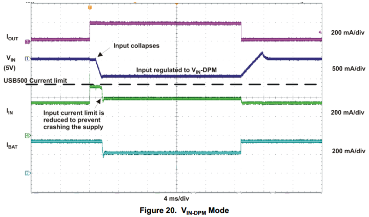
Figure 1When an external power source is connected, DPMM prioritizes the current demand of the system load.DPMM monitors the input voltage; if the input voltage drops below a certain threshold, the input current will be limited to prevent further reduction in input voltage, as shown in Figure 2.
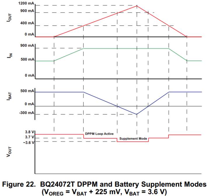
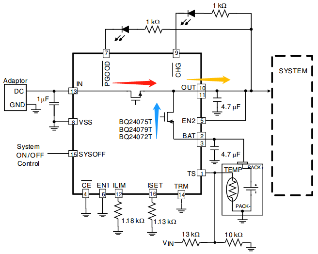
Figure 2When the sum of the charging current and the system load current exceeds the maximum input current limit, the output voltage will begin to drop. When the voltage drops to a certain threshold, the chip will enter DPMM mode. In this mode, the charging current for the battery will decrease while the current output to the load will increase to maintain the output voltage for the system load.If the battery charging current in this mode drops to zero, while the current output to the system load increases beyond the maximum input current limit, the output voltage will once again begin to drop. When the output voltage falls to a certain threshold, the battery will discharge current to supplement the system load until the output voltage rises above a certain threshold, at which point the battery will stop discharging to the system load. In the mode where the battery supplements the system load, the battery output current cannot be adjusted, but there will be short-circuit protection. The current waveform is shown in Figure 3, and the current flow direction is illustrated in Figure 4.
Figure 3
Figure 4Under normal circumstances, when the battery is fully charged, the battery switch will disconnect, allowing the external input power to supply the system load without drawing power from the battery, thus extending the battery life, as shown in Figure 5.
Figure 5
Related Articles:
Current Sensing Resistor Design in Battery Applications
An Overview of Lithium-Ion Battery Meter Principles
Recommended Reading:
Detailed Design Steps for Flyback Transformer Design
Fundamental Principles of Flyback Transformer Design
[Insights] Step-by-Step Explanation of Switching Power Supply Loop Compensation Design
[Super Insights] Easily Understand the Derivation of the Switching Power Supply TL431 Loop Transfer Function
Summary of Basic Knowledge on DDR
MOS Application with External Power Supply and Battery Power Dual Power Automatic Switching Circuit
Design of RC Snubber Absorption Circuit for BUCK Power Supply
Detailed Explanation of RLC Oscillation Principles in RC Snubber Absorption Circuits (Easy to Understand)
Power Supply Series: BUCK Inductor Operating Modes
Power Supply Series: BUCK Operating Modes under Light Load
Bipolar Transistor Switching Circuit Design
Understanding the Conduction Process and Loss Analysis of MOSFETs in One Article
Two Methods for Firmware Upgrade via IAP using Microcontrollers
-END-
Hello, I am Electronic Xiaobai, if you like my article, please give it a thumbs up and follow me.