1. Problem:
1. How to maximize available power for fast and efficient battery charging?
2. How to maximize power output while preventing power supply failure?
2. Definition and Understanding of DPM:
Dynamic Power Management (DPM) is a power management mechanism that allows dynamic management of power while the system is running. This is in contrast to traditional power management methods, which require the system to either suspend to save energy or resume operation to allow programs to function normally. This process typically requires user intervention (e.g., pressing a key), and the state switching is often very slow. In DPM, the system can turn off devices that are temporarily not in use, such as shutting down hard drives and displays. On the other hand, it can also dynamically adjust the CPU and bus frequencies based on the load to achieve energy savings. This is done dynamically without user intervention, and the switching between states is very fast (hundreds of times per second).
3. Classification of DPM:
3.1. DPM Based on Input Current
Figure 1 shows an efficient switching mode charger controlled by DPM. MOSFETs Q2 and Q3, along with inductor L, form a synchronous buck battery charger. Using a buck converter ensures effective conversion of the adapter’s input power for faster battery charging. MOSFET Q1 serves as a battery reverse-blocking MOSFET to prevent leakage current from the battery to the input through the body diode of MOSFET Q2. Additionally, it acts as an input current detector to monitor the adapter current.
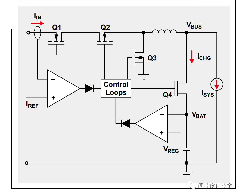
Figure 1: DPM Based on Input Current
MOSFET Q4 is used to actively monitor and control the battery charging current to achieve DPM functionality. When the input power is sufficient to support system load and battery charging, the ideal charging current value ICHG is used to charge the battery. If the system load (ISYS) suddenly increases and its total adapter current reaches the current limit setting (IREF), the input current regulation loop actively adjusts and maintains the input current at the predefined IREF input reference current. Higher priority is given to powering the system to achieve maximum performance while simultaneously reducing the charging current, thereby achieving the above goals. Thus, we can always maximize input power without crashing the input power supply while dynamically sharing the available power between the system and battery charging.
3.2. DPM Based on Input Voltage
If a third-party power supply is plugged into the system but the system cannot recognize its battery limitations, it becomes difficult to use DPM based on input current limits. In this case, we can use DPM based on input voltage (Figure 2). Resistor voltage dividers R1 and R2 are used to detect input voltage and feed it to the error amplifier of the input voltage regulation loop. Similarly, if the system load increases, causing the input current to exceed the adapter’s current limit, the adapter voltage begins to drop, eventually reaching the preset minimum input voltage. The input voltage regulation loop is activated to maintain the input voltage at the preset level. By automatically reducing the charging current to ensure that the total current from the input power source reaches its maximum (without crashing the power supply), this task can be accomplished. Therefore, the system can track the maximum input current of the adapter. The design goal of input voltage regulation is to keep the voltage sufficiently high to fully charge the battery. For example, the voltage can be set to around 4.35V to fully charge a single-cell lithium-ion battery pack.
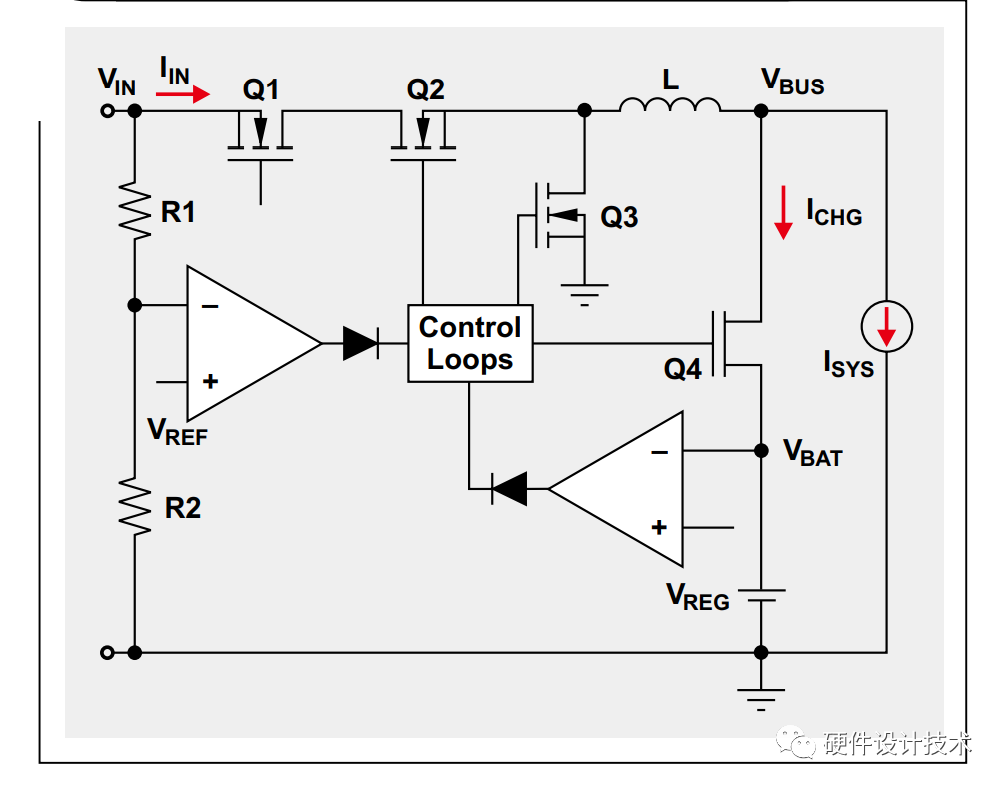
Figure 2: DPM Based on Input Voltage
3.3. Battery Supplement Power Mode
DPM based on input current or input voltage can obtain maximum power from the adapter without crashing the power supply. For some portable devices, such as smartphones and tablets, the system load is often dynamic and has high pulse currents. Even if the charging current has dropped to zero, what if the peak power of the system with pulse current exceeds the input power? If not actively controlled, the input power supply may crash.
One solution is to increase the rated power of the adapter, but this will increase the size and cost of the adapter. Another solution is to enable MOSFET Q4 to discharge the battery instead of charging it, temporarily providing more power to the system. By combining DPM control and battery supplement power mode, the adapter can be optimized to provide average power rather than maximum peak system power, thereby reducing costs and achieving the smallest solution size.
4. Differences Between DPPM (Dynamic Power Path Management) and VIN DPM (Input Voltage Dynamic Power Management):
4.1. Dynamic Power Path Management (DPPM)
DPPM is another function of power path devices. It can monitor the input voltage and current of the device and automatically prioritize the system when the adapter cannot support the system load. The input source current is shared between system load and battery charging. If the system load increases, this function can reduce the charging current. When the system voltage drops to a certain threshold, the battery can stop charging and discharge to supplement the system current requirements. This feature’s implementation can effectively prevent system crashes.
4.2. Input Voltage Dynamic Power Management (VIN-DPM)
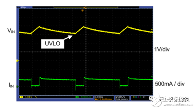
Another function that is often confused with DPPM is VIN-DPM. This mechanism sounds very similar, but the focus is entirely different. The input power or adapter has a rated power. In some cases, the input power is insufficient to meet the device’s demands. In USB standards, designers are increasingly aware of this issue. Devices being charged may require compatibility with various types (even unknown) adapters. If the input source is overloaded and causes the input voltage to drop below the undervoltage lockout (UVLO) threshold, the device will shut down and stop charging. Once the power load disappears, the adapter recovers. Its voltage rises above UVLO and resumes charging, but the adapter will immediately overload and crash again. This adverse situation is known as “hiccup mode.” See the diagram below.
The DPPM function can successfully solve this problem because it continuously monitors the input voltage of the charger. If the input voltage drops below a certain threshold, VIN-DPM adjusts the charger to reduce the input current load, thus preventing the adapter from crashing.
4.3. Similarities and Differences: