It is common to see pull-up and pull-down resistors connected to the D+/D- lines of USB interfaces on some development boards, while others do not connect anything at all. This can be quite confusing.
On the official USB protocol website, http://www.usb.org/developers/docs/usb20_docs/#usb20spec
I checked the resistor_ecn document.
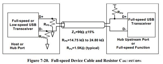
First, the USB bus can have both idle and transmit states.
Initially, the USB host will check the status of the bus; if both lines are low, it indicates that there are currently no devices requesting to connect. Therefore, the host side has two pull-down resistors set by default to indicate idle state.
The pull-up resistors on D+/D- indicate whether the USB device is low or full/high speed. A pull-up on D+ indicates a full/high speed device, while a pull-up on D- indicates a low speed device.
The values for pull-up and pull-down resistors have a fairly large range, which is detailed in the specifications. Typically, the host’s pull-down is 15K, and the device’s pull-up is 1.5K, with a tolerance of 5%. However, some designs may utilize a Thevenin match at the end to improve signal quality, and the device side may also have a pull-down.
The pull-up is to a 3.3V level, with a range of 3.0V to 3.6V. If there is a Thevenin match, the lower value can go down to 2.7V. A 7.2K resistor can also be used to pull up to a 5V level. It seems that the latest specifications have been updated to allow a lower value of 2.7V.
If the high level on the D+/D- lines disappears for more than 2.5us, the bus releases the device into idle state.
In designs, the pull-up to the 3.3V level is often used directly, and some may use transistors or MOSFETs in series with resistors to control the state. I plan to use an STM32 IO to control this level directly.
There is a very good research document: https://wenku.baidu.com/view/98d223156c175f0e7cd13766.html?re=view
“Research on Pull-Up Resistor Functions on USB Device Side”
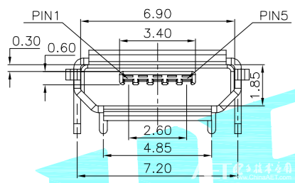
Micro USB Receptacle (viewing from the left, pin 1 is on the left)
Plug head (both male and female connectors have AB types)
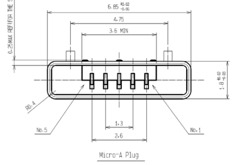
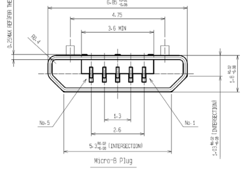
|
Pin |
Name |
Wire Color |
Description |
|
1 |
VBUS |
Red |
Power positive 5 V |
|
2 |
D− |
White |
Data line negative |
|
3 |
D+ |
Green |
Data line positive |
|
4 |
ID |
None |
Supports OTG function A: Ground, host B: Floating, device |
|
5 |
GND |
Black |
Signal ground |
Low-Speed (1.5Mb/s), Full-Speed (12Mb/s), High-Speed (480Mb/s)