Total words: 4091, 54 imagesEstimated reading time: 11 minutes
This article is about DIY self-balancing robots, and I will show you how to build your own self-balancing robot.
This article is about DIY self-balancing robots, and I will show you how to build your own self-balancing robot.I attempted to build the project but did not achieve the expected results. However, the performance of this robot is quite good and accurate, even though it is not perfect compared to my previous robots.
I used a custom PCB, Arduino Nano, MPU6050, A4988 driver, HC-05 bt module, MDF board, and some hardware to build this self-balancing robot. A detailed list of materials can be found in this article. This project usesBalancingwiifirmware andEZ-GUIandroid application to control the robot via Bluetooth. Download link: https://51qudong.lanzous.com/ibgf1qj, long press the QR code to download directly:
So, let’s start with some basics of self-balancing robots.

Video

Basics of Self-Balancing Robots
A self-balancing robot refers to a robot that balances on two wheels by continuously correcting its position.
Gyroscope sensors are used in self-balancing robots, which continuously send the robot’s directional data to the controller.
Based on this data, the controller commands the motors to run forward or backward to keep the robot upright.

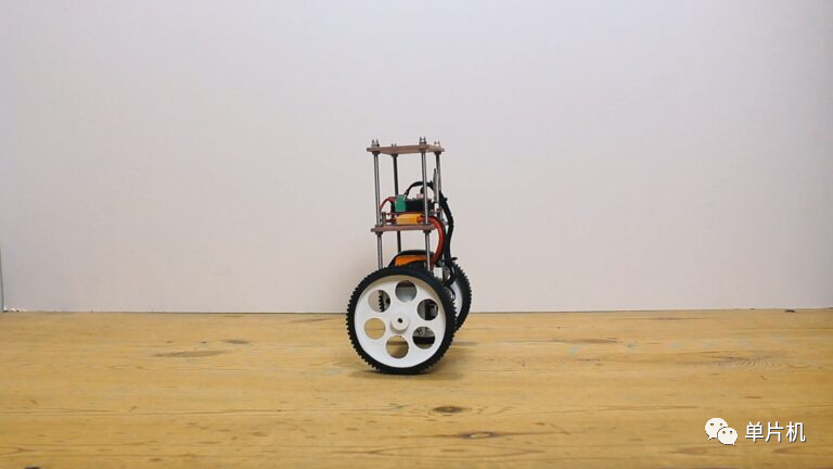
This is the ideal position for the self-balancing robot, with the body perfectly upright over the wheels. The angle between the Y-axis and the robot’s body is zero.

When the body tilts forward, there will be an angle between the Y-axis and the body.The MPU6050 gyroscope sensor detects this angle and sends this data to the Arduino.The Arduino now performs PID calculations and commands the stepper motorto run forward to minimize the tilt angle to zero degrees.

If the robot tilts backward, the motor will also rotate backward to correct the tilt angle to zero, the same situation occurs. The robot continues to reverse the motor at a speed of 400 times per second, so we see that the robot remains stable in this position.

Required Components
-
Arduino Nano………………………..1piece
-
MPU6050 Gyroscope Sensor……………….1piece
-
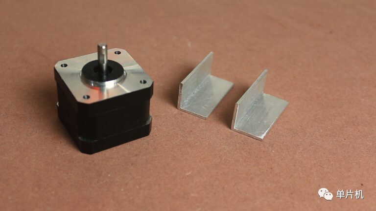
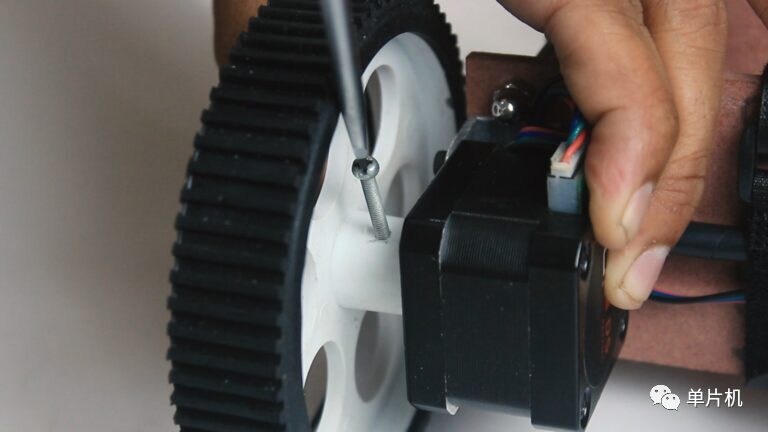
Nema 17 Stepper Motor………….2pieces
-
100mm Wheel…………………………..2pieces
-
A4988 Stepper Driver IC…………..2pieces
-
HC-05 Bluetooth Module………… 1piece
-
4mm MDF Board
-
150mm M5 Threaded Rod – 4 pieces
-
Some Nuts and Bolts

DIY Self-Balancing Robot Electrical Diagram

The above image is the circuit diagram of the self-balancing robot.
I have prepared a PCB, you can also download the Gerber file to order the PCB or edit the PCB on the easyeda platform.https://easyeda.com/sharmaz747/self-balancing
Note: - Please cross-check your product before ordering the PCB.


The basic connections and minimum connections you need are as follows:
I2C:
-
A4 – SDA
-
A5 – SCL
Motor Driver Pins:
-
D5 – STEP1 (PORTD 5)
-
D6 – STEP2 (PORTD 6)
-
D7 – DIR1 (PORTD 7)
-
D8 – DIR2 (PORTB 0)
-
D4 – Enable (applies to all)

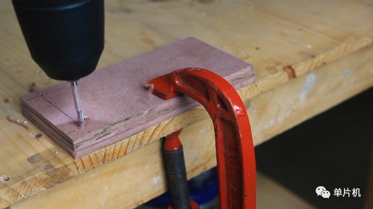
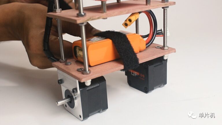
Robot Construction
Below is the basic construction diagram of the self-balancing robot.

I
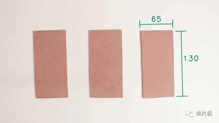
cut three pieces of size 130 x 65mm from 4mm thick MDF board
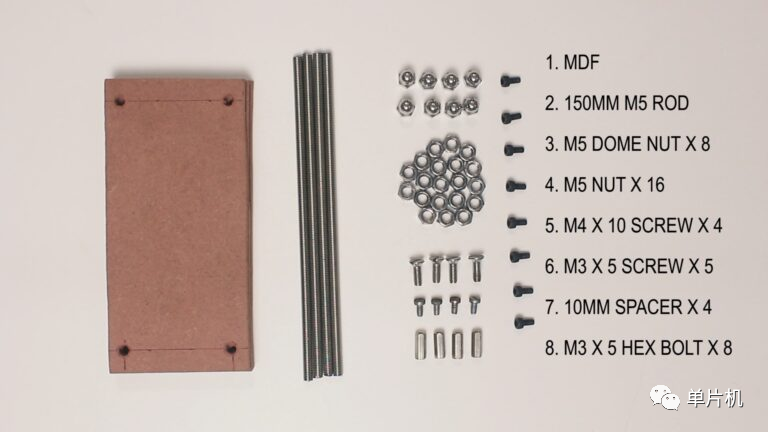
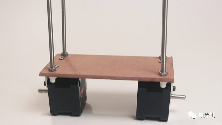
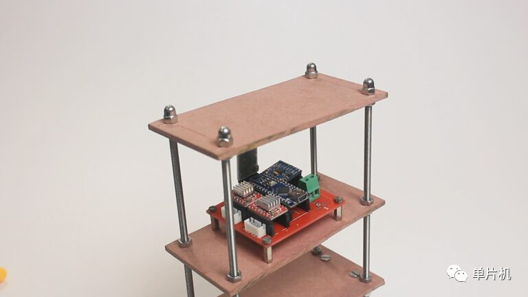
And placed the PCB on the middle platform on 10 mm spacers.
Now we can proceed to program the self-balancing robot.

Programming
Downloadbalancewii:https://github.com/mahowik/BalancingWii
To start programming the Arduino, we need to download a firmware calledbalancewii for the balancing robot.
This firmware is based on the Multiwii firmware used for quadcopters and multirotors. You can learn more aboutMultiwii here: http://www.multiwii.com/wiki/index.php?title=Main_Page.
Special thanks to the developer of this firmware,Mahowik: https://github.com/mahowik
Download firmwarebalancewii:https://github.com/mahowik/BalancingWii, now click the green button to clone or download. The firmware will be downloaded to your PC in ZIP format.

Now unzip the downloaded file, open the newly created folder, and delete the three files highlighted in the image, which are not needed at all.
Also, the folder containing the balancewii.ino file must have the same name; otherwise, you will get a compilation error.
Now, open the balancedwii.ino file in Arduino, compile the code and upload it without making any changes.
Before uploading the code, do not forget to turn off the BT module.
If your MPU6050 orientation is different, then I need to change this line in the config.h file.You can change PITCH to ROLL here
-
#define CURRENT_AXIS PITCH // You can choose ROLL or PITCH axis as the current axis.
By default, most HC-05 BT modules come with a default baud rate of 9600.
But for this project, please note that the baud rate of your HC-05 BT module must be 115200; otherwise, you will not be able to connect to the android application.
You can change it by AT commands; search on Google for the baud rate of HC-05 bt module, and you will find many tutorials about it.
-
/ * This is the speed of the serial interface * /
-
#define SERIAL0_COM_SPEED 115200
-
#define SERIAL1_COM_SPEED 115200
-
#define SERIAL2_COM_SPEED 115200
-
#define SERIAL3_COM_SPEED 115200
If you think the robot’s response speed is slow, you can try changing this setting in the config.h file, but remember that these values must be constrained.
-
#define MAX_SPEED 350 // should <= 500
-
#define MAX_TARGET_ANGLE 130 // where 10 = 1 degree, should <= 15 degrees (i.e., <= 150)
-
#define MAX_STEERING 90 // should <= 100
Android Application
The EZ-GUI application is what we will use here, you can learn more aboutEZ-GUI (http://ez-gui.com/) from here.The EZ-GUI application can be downloaded for free from the Play Store by clicking the following or scanning the QR code link below. The above download package has included this apk file.
https://play.google.com/store/apps/details?id=com.ezio.multiwii

Application Settings
Open the downloaded application, then click the three dots in the upper right corner of the screen, click settings.
Select the BT device to choose the BT module, now click the NEXT button
Now, from the list, select the firmware “ Multiwii 2.40”, and then click “Next” until you reach the main screen.

Click the “Connect” button to connect via Bluetooth.

Press the “AUX” button

Scale markings are as shown above.

This is my PID settings
The PID settings are not mandatory for your robot; each robot is unique.The PID depends on the robot’s design, center of gravity, wheel size, motor type, etc. Try different settings, and after some attempts, you will definitely get the best settings.
Now return from this screen, click the three dots in the upper right corner, go to “Advanced”, then to “Untested”, and then click “Model Control”

Now, this is the screen where you can play with your robot; you can run the self-balancing robot from the joystick, and on this screen, try different settings to learn more.
Thus, our DIY self-balancing robot is ready to play.If you have any questions, please ask in the comments section.Click to read the original link.
Below are the comments from the original text.


https://www.omc-stepperonline.com/nema-17-stepper-motor/big-sale-nema-17-bipolar-1-8deg-26ncm-36-8oz-in-0-4a-12v-42x42x34mm-4-wires-300mm-length-cable.html
Source: Microcontroller