MAKER: Shebin Jose Jacob, Nekhil / Translated by: Fun Endless
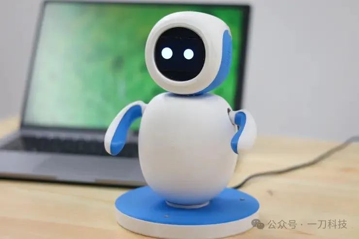
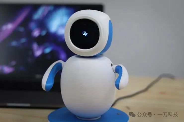
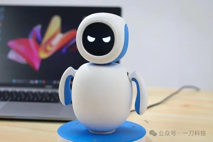
Introduction Emo is a personal companion robot that embodies style and innovation. Its creation is made possible by the latest Raspberry Pi 4 technology and advanced design. It is not just a robot; it is a living presence. Unlike other robots, it possesses a unique personality and emotions that can capture your heart.
Hardware Section
– Raspberry Pi 4B– Micro Snow 2-inch IPS LCD Display (240×320 resolution)– SG90 Servo ×2– MG90 Servo– 16-channel 12-bit PWM Servo Driver Board– 801S Vibration Sensor Module– Single-channel TTP223 Touch Sensor Module– 8 Ω 0.5 W Speaker Module– PAM8403 Dual-channel Stereo Audio Amplifier Module– 5 x 7cm Double-sided Universal PCB Prototype Board– 40-pin 2.54mm Male-Female Header Connector (Separated Pin Socket)– 304 Stainless Steel CSK Countersunk Phillips Bolt M2 ×10– M3 x 10mm CHHD Bolt Nut Kit– M3 x 20mm CHHD Bolt Nut Kit– B-30-1000 PCB Flying Wire (with PVC insulated outer layer)– 2mm Thick Acrylic Board
Software Section
– Autodesk Fusion 360– Microsoft VS Code
Tools Section
– Multi-functional Screwdriver– Soldering Iron– Lead-free Solder Wire– PCB Welding Fixing Clamp– Flux– Multi-functional Wire Stripper– Hot Glue Gun
Design Concept
We used Autodesk Fusion 360 to design the Emo robot, incorporating both solid and freeform modeling techniques.

 To simplify the printing process, we divided the robot’s body into several parts for easy assembly with screws.

We carefully considered the position of the power supply, placing it on the base and leaving ample space for the power cord to move freely. To enhance the robot’s movement stability, we also ensured that the body slightly contacts the base.
Additionally, we specifically chose a blue and white color scheme because the blue and white combination enhances the robot’s visual appeal.
3D Printing
We chose PLA as the 3D printing material and printed each component separately, which takes a long time.
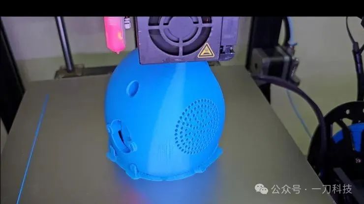
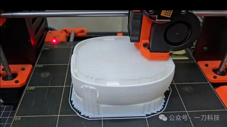
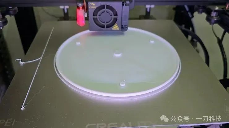
To enhance the durability of the base, we set the filling density of the base to 40%, while other parts are set to 20%.
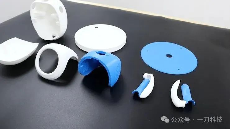
Now that we have printed all the parts, let’s start the assembly process together!
Assembling the Base
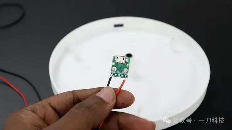
First, we will install the Micro USB module on the base, which will serve as the robot’s power supply interface.
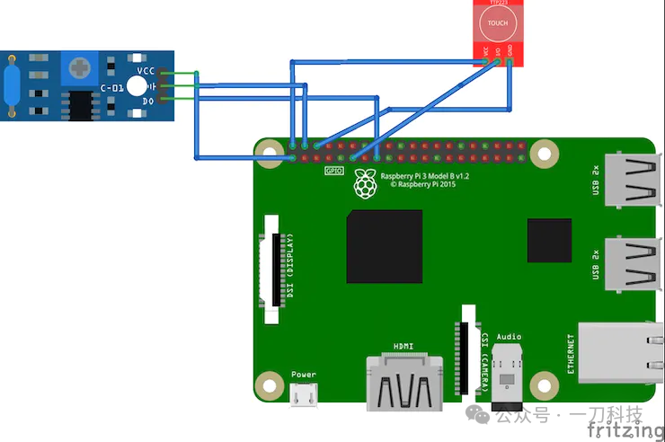
We placed the SW-420 vibration sensor near the USB module; it can detect any vibrations occurring around the robot.
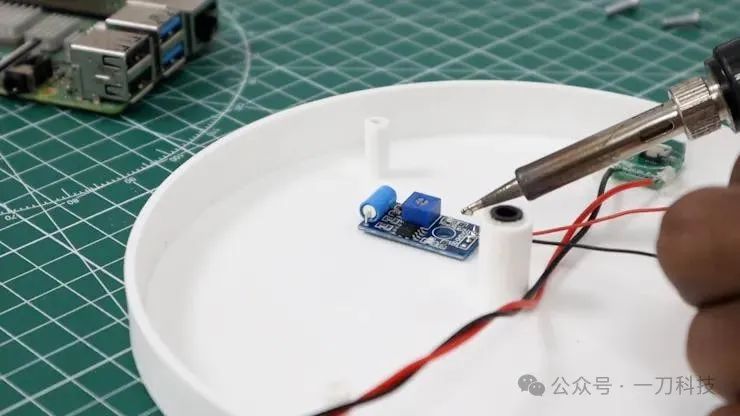
The base section consists of three wires: VCC, GND, and the output wire of the vibration sensor.
Finally, we securely fastened the lid to the base using M3 x 10 mm bolts. Thus, we have completed the assembly of the base section.
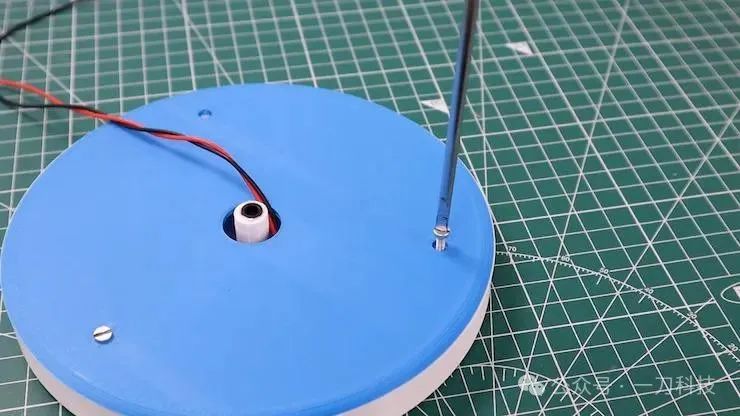
Assembling the Head
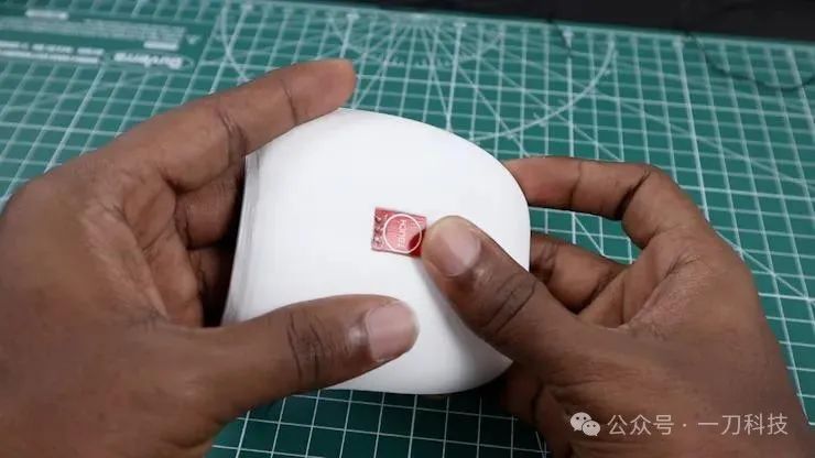
To give the robot’s head touch capabilities, we used a compact capacitive touch sensor and perfectly embedded it in the designated area.
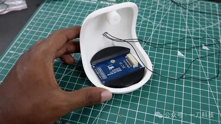
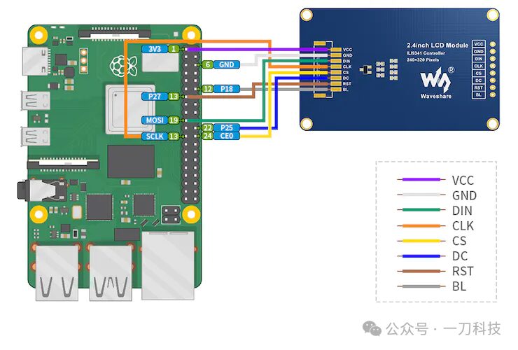
The core component of the robot’s head is a Micro Snow 2-inch IPS display, which plays an important role in conveying the robot’s emotions. We secured this display with a black bracket and a small amount of hot glue.
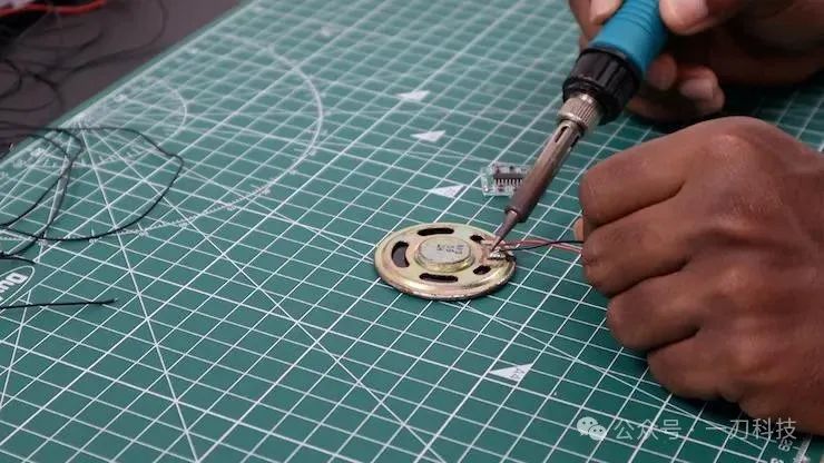
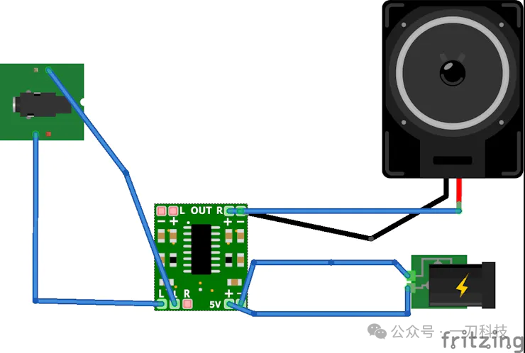
To achieve audio playback functionality, we integrated an 8 Ω 0.5 W speaker on the left side of the head, paired with a PAM8403 amplifier to amplify the sound from the Raspberry Pi.
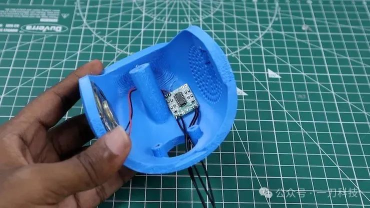
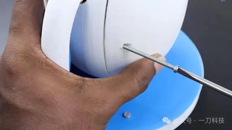
Next, we used M3 x 15 mm screws to securely attach the lower half of the head to the robot’s body. Then we connected the previously assembled upper half of the head, completing the entire head assembly.
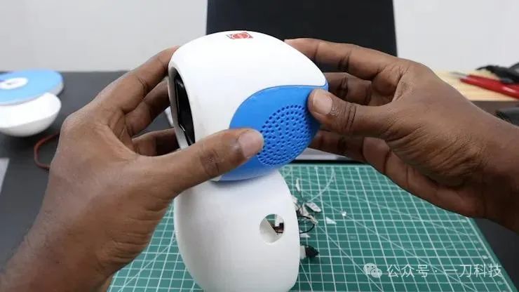
Assembling the Body
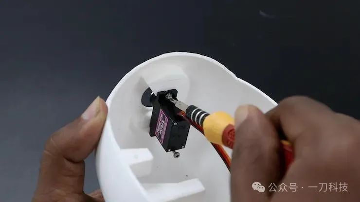
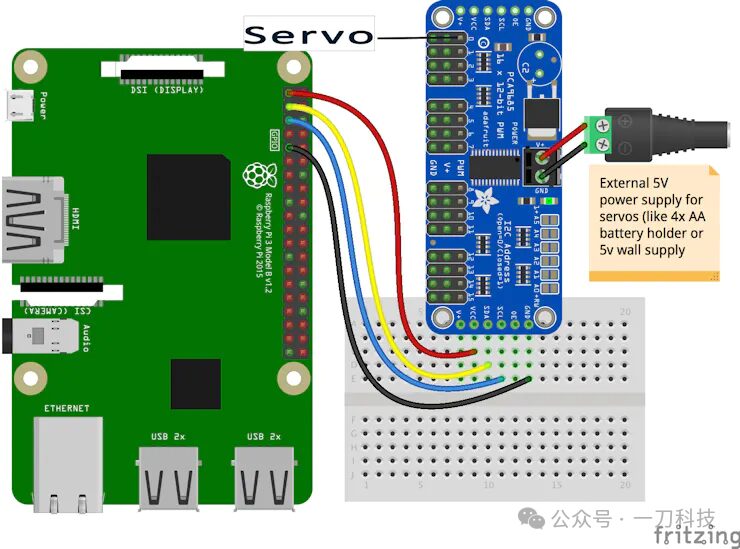
In the body section, we installed three servos: two SG90 servos for the hands and one MG90 servo for body rotation. To conveniently control these servos, we used the PCA9685-16 channel servo driver.
To ensure stability, we also fixed the MG90 servo to the front of the body using M2 nuts and bolts.
We placed the PCA9685 module in the same area to effectively balance the weight.
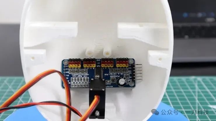
Now we start assembling the robot’s hands. Simply install the SG90 servos at both ends and secure them firmly to the servo shafts to complete the assembly.
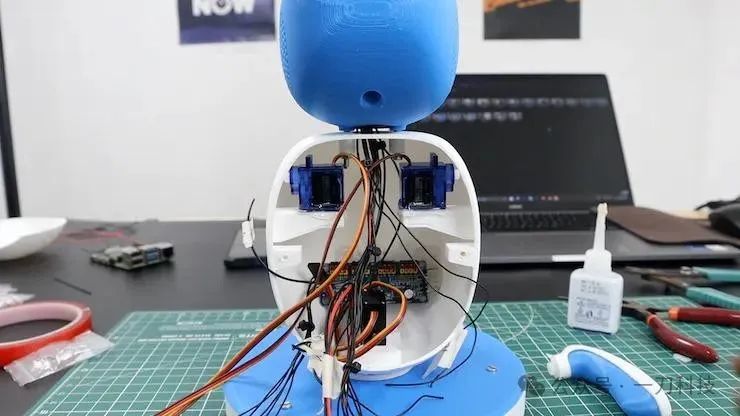
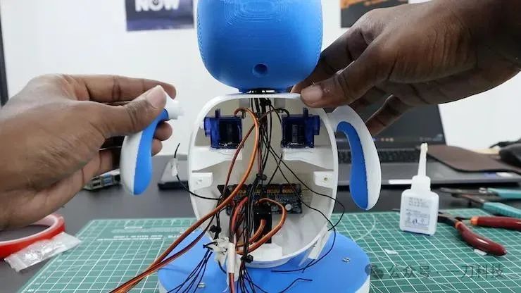
We used a prototype board with female headers to connect the Raspberry Pi, which is more efficient than using wires. Additionally, by soldering, we ensure that all components are correctly connected, minimizing the possibility of wire tangling.
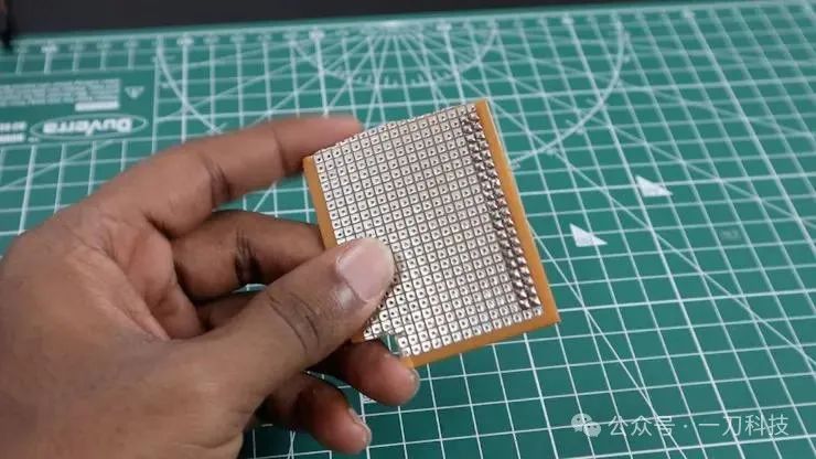
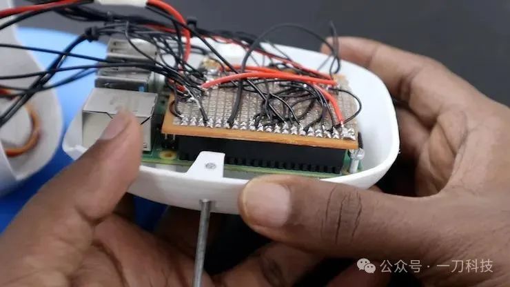
To save space, we used a male USB Type-C board from a mobile charger to power the Raspberry Pi. For audio transmission, we adopted a TRS audio jack.
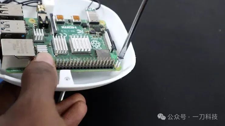
Finally, we secured the Raspberry Pi to the back of the body with bolts, completing the power installation.
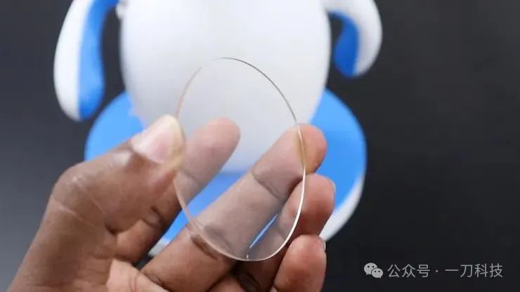
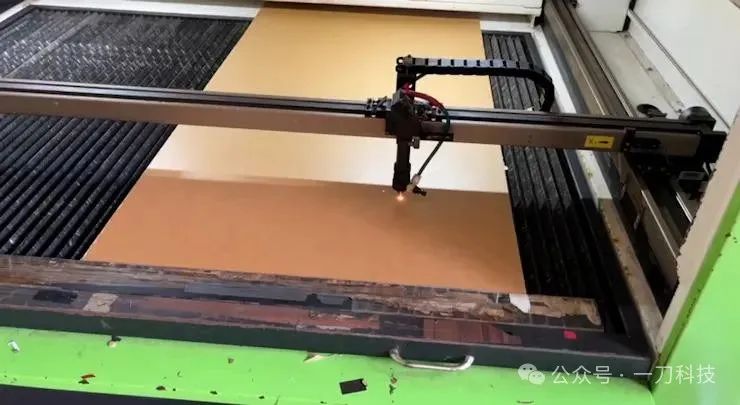
Additionally, we used a 2 mm thick transparent acrylic board on the front, which can cover the gap between the outer cover and the LCD module.
Circuit Section
Wiring as shown below:
Programming
Next, we start writing the code to generate emotions, where the servo movements and animations are the core components. To achieve these complex functions, we used Python’s `multiprocessing` package, which enables the robot to execute multiple tasks simultaneously, thereby improving operational efficiency.
It is worth mentioning that we used Adobe After Effects software to create animations and exported them as image sequences, making it easier to integrate into the overall system.
Debugging
After programming, to ensure the robot operates correctly, we need to test all components.
First, install the required dependencies:
|
|
<span>pip install adafruit-blinka adafruit-circuitpython-servokit</span> |
Enter the code folder (Code) and execute the following command to start the program:
|
|
<span>python3 final.py</span> |
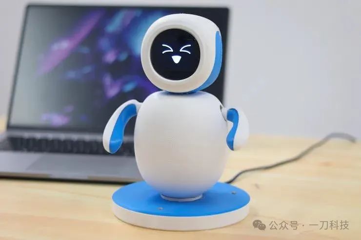
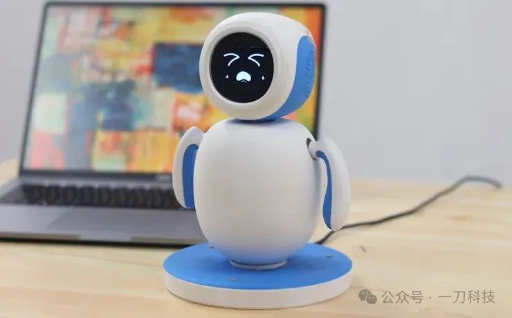
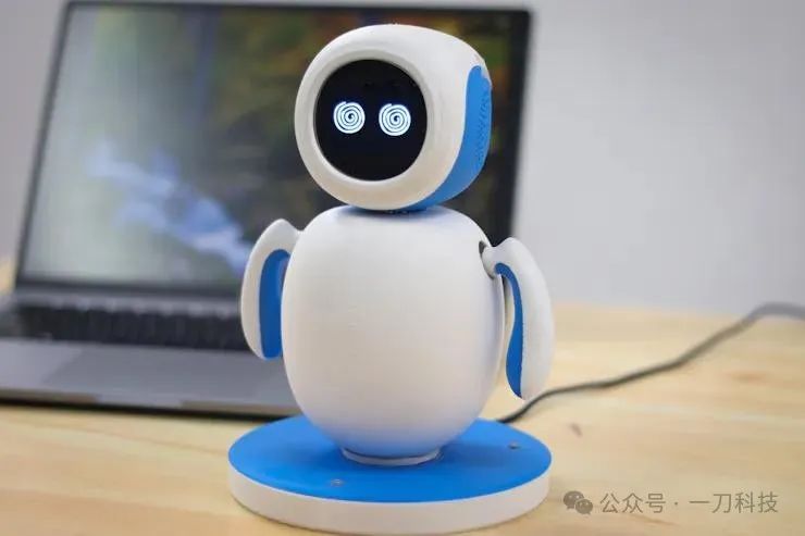
Now your Emo robot is up and running! When you say something to it, it will analyze your tone and display the corresponding expression on the screen.
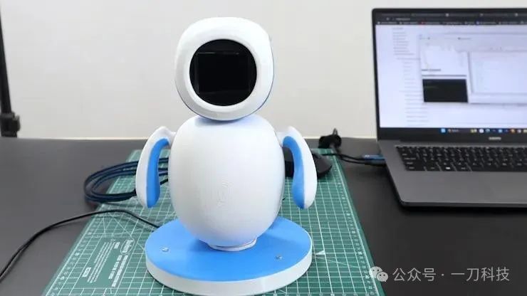
Results
The moment to witness the miracle has arrived!
