For the layout of components on the universal board, most people are accustomed to “following the clues,” which means centering around key components like chips and inserting other components as needed. This method reflects order in chaos while being efficient. However, due to a lack of experience, beginners may find this method unsuitable. Beginners can first prepare a preliminary layout on paper, then draw it on the front side of the perforated board (the component side) with a pencil, allowing for easier soldering planning.
As for the soldering method for universal boards, it generally involves using the fine wires mentioned earlier for flying connections. There isn’t much skill involved in flying connections, but it’s best to keep the wiring horizontal and vertical, as shown in the picture below.

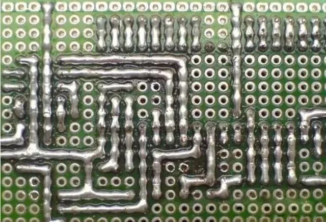
Another popular method online is the soldering wire connection method, as shown in the picture below. The process is good, and the performance is stable, but it wastes solder. Pure solder wire connections are more challenging and are influenced by factors such as solder wire and individual soldering skills. If you first pull a thin copper wire and then drag weld along it, it becomes much easier. The soldering method for perforated boards is very flexible; it varies from person to person, and you should find a method that suits you.
Many beginners find their soldered boards unstable, prone to short circuits or open circuits. In addition to irrational layout and poor soldering, a lack of skills is one of the significant causes of these issues. Mastering some techniques can significantly reduce the complexity of reflecting the circuit in physical hardware, decrease the number of flying wires, and make the circuit more stable. Below, based on my experience, I will discuss soldering techniques for perforated boards.
1. Preliminary Determine the Layout of Power Supply and Ground
The power supply runs through the circuit, and a reasonable power layout plays a crucial role in simplifying the circuit. Some perforated boards have copper foils running through the entire board, which should be used as power and ground wires; if there are no such copper foils, you also need to have a preliminary plan for the layout of power and ground wires.
2. Make Good Use of Component Pins
Soldering on perforated boards requires a lot of jumpers and connections. Don’t rush to cut off excess pins from components; sometimes connecting directly to the surrounding component pins can be much more efficient. Additionally, to save materials, you can collect the cut component pins as materials for jumpers.
3. Be Good at Setting Jumpers
This point must be emphasized: setting more jumpers can simplify connections and make them look much neater, as shown in the picture below.

4. Be Good at Utilizing the Structure of Components Themselves
Figure A shows a matrix keyboard circuit, and Figure B is a matrix keyboard soldered by the author. This is a typical example of utilizing the inherent structure of components: the tactile switches in Figure B have four pins, two of which are connected, allowing us to use this feature to simplify connections, with the electrically connected pins acting as jumpers. Readers can compare with Figure C to appreciate this.

Figure A

Figure B
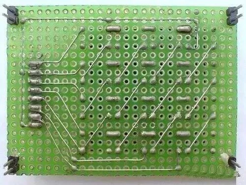
Figure C
5. Be Good at Utilizing Pin Headers
I like using pin headers because they have many flexible uses. For example, when connecting two boards, you can use pin headers and sockets, which serve both mechanical and electrical connection purposes between the two boards. This draws on the method of connecting computer circuit boards.
6. Cut Copper Foil When Necessary
When using a perforated board, to make the most of the space, you may need to use a knife to cut a portion of the copper foil so that more components can be placed in the limited space.
7. Make Full Use of Double-Sided Boards
Double-sided boards are relatively expensive, so if you choose them, you should make full use of them. Each pad on a double-sided board can act as a via, flexibly achieving electrical connections on both sides.
8. Make Full Use of the Space on the Board
The chip sockets hide components, making them both aesthetically pleasing and protective.


The comparison between the circuit boards made by beginners and experts is shocking!
The boards made by entry-level newcomers look like this ▼


The boards made by experts look like this ▼

Of course, there are also experts who can create beautiful designs without using boards;


Some can even build super complex designs,
Foreigners have built a CPU using logic gates on a universal board… it’s simply amazing!

Preparation Work
1. Drawing and Simulating the Schematic

Key Points:
(1) Divide the circuit into blocks to provide a rough functional partition for layout and soldering;
(2) Parameters of key points [inputs, outputs of each circuit block, special points, etc.] provide reference values for circuit debugging;
2. Preparing Components

Key Points:
(1) Check the component values and labels to avoid omissions;
(2) Ensure that components and consumables are ready before starting; avoid scrambling at the last minute;
(3) Test components as much as possible before soldering;
3. Preparing Tools


A good soldering iron is essential; it is recommended to use a temperature-controlled soldering station;
4. Installing Copper Pillars
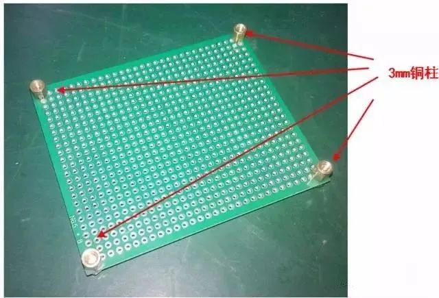
Installing copper pillars (or screws) at the corners can effectively prevent accidental short circuits on the soldering surface.
Pre-layout
1. Arrange Important Components and Interface Devices

The layout should be reasonable, easy to operate, compact, and facilitate connections and soldering.
2. Consider Signal Flow Direction

Signals should flow sequentially on the circuit board to avoid crossing.
3. Record Layout and Remove Components

Use a pencil to record the positions of key components, the general layout, and the signal flow direction.
Building the Power Supply Section
1. Build the Power Supply Section

First solder and debug the power circuit, which is the first step to ensure overall normal operation.


A good layout makes wiring very easy.

The power supply section must be debugged and tested before proceeding with the subsequent circuit construction.
2. Build the Signal Processing Section

Generally, start building from the source of the signal flow, measuring while building.

After completing a circuit module, immediately test it against simulation or theoretical values.
Always build in modules and test simultaneously; avoid soldering everything at once.

Once the current module is tested correctly, proceed with the construction and testing of adjacent modules.

Using similar methods, sequentially build the remaining circuit modules (testing simultaneously).
3. Complete Soldering

Check solder joints, correct poor solder joints, tidy up messy wiring, and finish up.
4. Overall Circuit Testing

Test functionality and indicators (such as accuracy) to verify compliance with overall design goals.
Organizing Materials
1. Draw the Official Circuit Diagram
(1) Were there any changes? If so, they should be reflected in the final circuit diagram.
(2) Mark key testing points.
2. Testing Report
(1) Organize raw test data into tables;
(2) Calculate errors, precision, and other indicators, comparing them with theoretical values;
(3) Did the indicators and functions meet the expected design requirements?
Appreciation of Qualified Circuit Building Works
Excellent works = Integrity, Independence, Aesthetics, Testability
Disclaimer: This article is reproduced from the internet, and the copyright belongs to the original author. If there are any copyright issues, please contact us in time to delete it, thank you!
Three must-have tools for electrical workers, easily accessible via WeChat!
[Bookmark] The “Path” of a ten-year veteran electrician, the secret to earning over ten thousand a month!
Five major electrical drawing software (CAD, Eplan, CADe_simu…), which one do you pick?
The latest electrical CAD drawing software, including a super detailed installation tutorial!
The latest electrical drawing software EPLAN, including a super detailed installation tutorial!
Common problems for beginners using S7-200 SMART programming software (including download links)
Comprehensive electrical calculation EXCEL sheets, automatically generated! No need to ask others for electrical calculations!
Basic skills for PLC programming: Ladder diagrams and control circuits (including 1164 practical cases for Mitsubishi PLC)
Can’t understand electrical diagrams yet? Basic electrical diagram recognition, simulation software available, quickly get started with theory and practice!
12 free electrician video courses, 10GB software/e-book materials, and 30 days of free electrician live classes are being given away!