Source: https://blog.csdn.net/qq_34430371/article/details/125820927
Compiled by: Technology Makes Dreams Greater | Li Xiaoyao
The author discusses the understanding and insights regarding ARM general purpose registers and status registers.
ARM General Purpose Registers
For processors, registers can serve as temporary storage for holding intermediate results, as input data for computations, or as an index for accessing memory, with various functions.
CortexM3/M4
CortexM3/M4 is a commonly used ARM architecture, adopted by many manufacturers, such as STMicroelectronics’ STM32, which is widely popular, and NXP’s MK60 chip, which has been favored in Freescale competitions. Additionally, domestic companies like GigaDevice’s GD32, Aoteli’s AT32, and National Technology’s N32 series are also notable.
It is very popular in the embedded field, relatively easy to get started with, fully functional, and meets general MCU requirements.
The register model is as follows: 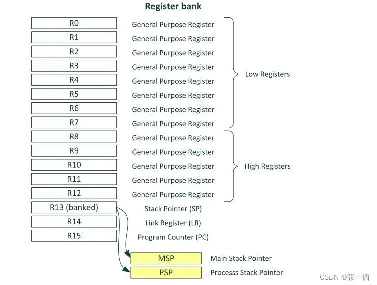
-
General purpose registers R0-R7
, low group registers, 32-bit, accessible by both 16-bit Thumb and 32-bit Thumb-2 instructions
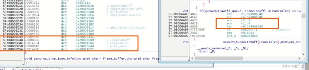
- It can be seen that R0, R1, and R2 are used as parameters passed in.
- Later, R0 is used to output the result for comparison.
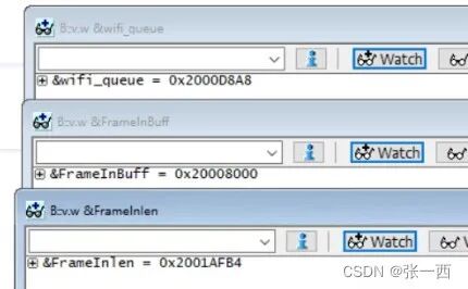
- The input parameter is an array; why not directly pass the address (LDR), but instead use the DCD instruction?
- This is because the range of LDR for address fetching is limited, LDR Rn, #immediate address, this address is only a small range (4KB?), so we can see that the address of DCD is not far away (6A92 – 6D48 is not far apart), while the memory address is in the range of 2000000, which is quite different from its address. From Figure 2, we can see that the address after DCD is actually addressed first through the DCD address, and then used as an address for further addressing.

- R0-R3 are generally used for parameter passing; if there are more parameters, they are passed via stack.
- R0 and R1 will also be used to pass return values; if it is 32-bit, it is R0, and for 64-bit, it will use R0-R1
-
General purpose registers R8-R12
, high group registers, 32-bit, accessible by fewer 16-bit Thumb instructions, generally accessed by Thumb-2 instructions.
- R11 is generally used as the FP pointer, saving the stack frame (when adding compilation options, see the previous article, the same applies to SP and LR in the following ARM development common registers explanation).
-
Stack Pointer R13 (SP) indicates the current position of the stack.
-
Link Register R14 (LR) saves the program return address.
-
Program Counter R15 (PC)
indicates the current position of program execution.
- In the following figure, PC serves as the base address, then accesses memory, 0x4079a1c+480 =0x4079c04
- In the next figure, directly gives 0x4079c04 as the address to r0
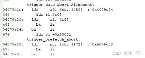

- Instructions must be aligned to half-word or word addresses, with the least significant bit being 0.
- Special jump instructions require the PC’s least significant bit to indicate Thumb state; otherwise, an exception will be triggered.
- Sometimes, the PC serves as a base register, then adds an address offset to access data.
CortexR5
The Cortex R series inherits the system model under the ARM7 architecture, with multiple working modes, each having its own address space (stack address SP) 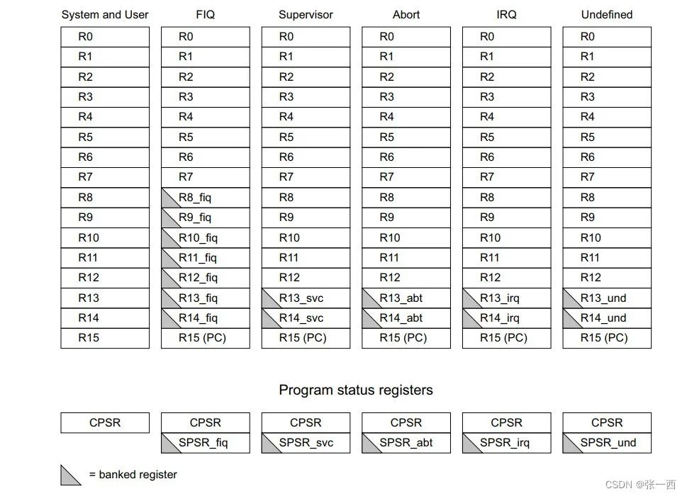
- CortexR5 belongs to the ARMv7 instruction set.
- It has the same functions for R0-R7 and R8-R12 as CortexM3/4.
- User mode and sys mode share a set of registers, i.e., they are shared.
- In user/sys, FIQ, SVC, ABT, IRQ, and UND modes, LR, SP, and SPSR are independent; after switching CPSR modes, SP, LR, and SPSR automatically switch to the corresponding mode’s register values.
- FIQ is called a fast interrupt because it has independent R8-R12 registers, which do not require stack operations and can be used directly.
- SPSR saves the CPSR of the previous mode.
The general AR series register model of ARMv7 is fundamentally the same as above, with some new extensions.
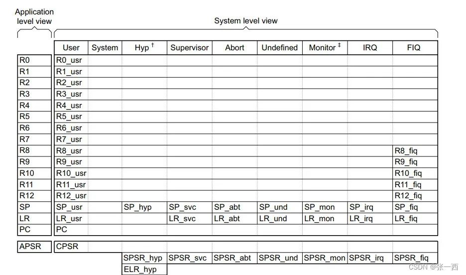
- Hyp mode and Mon mode have been added, used for virtual extension and security extension, respectively.
- In Hyp mode, LR is ELR, which records the return address during exceptions; others remain consistent.
CortexA53
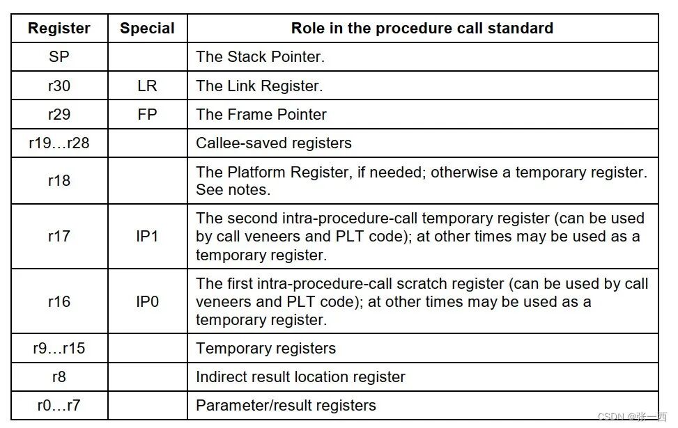
- r0-r7 are used for parameter passing or returning results.
- r8 is an indirect result location register.
- r9-r15 are temporary registers for storing intermediate results.
- r16-r17 are registers needed for dynamic linking (not all addresses can be jumped to) (code inserted internally by the linker).
- r18 is a register dedicated to the Platform ABI for saving internal program states (to ensure platform compatibility, avoid usage).
- r19-r28 are callee-saved registers (there are also caller-saved registers, well represented in CortexM3/4).
- r29 is the FP register, requiring compilation options.
- r30 is the link register.
- SP is the stack pointer.
- PC is the program register,
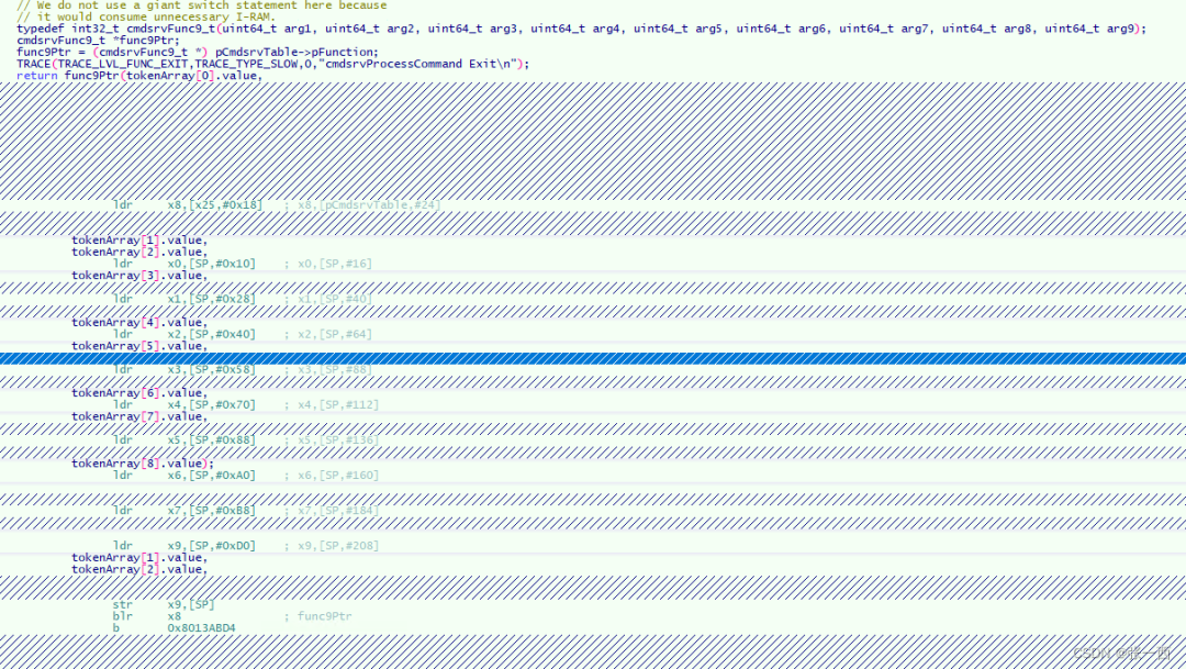 It can be seen that when the program is called, the function type has 9 parameters, assembly code x0-x7 is passed in as parameters, and the last parameter is passed via stack, str x9,[SP]. It also uses blr to perform link jumps through registers and finally returns via b jump.
Status Registers
Registers typically refer to CPSR (Current Program State Register), which indicates the current state of program execution, mode, operation result status, interrupt status, etc. For example, the following CPSR register model. 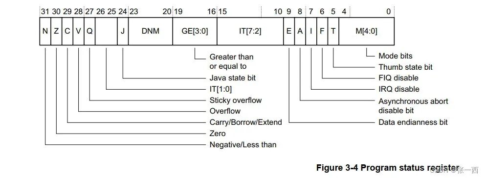
Flag Field
Explanation: Indicates the status of the program’s execution result, which can be used for branching, e.g., whether the result is 0, whether there is a carry, whether there is an overflow, whether the result is negative, etc. 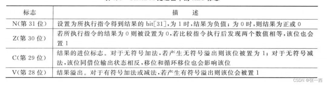
- Flags include NCVZ, representing Negative, Carry, Overflow, and Zero.
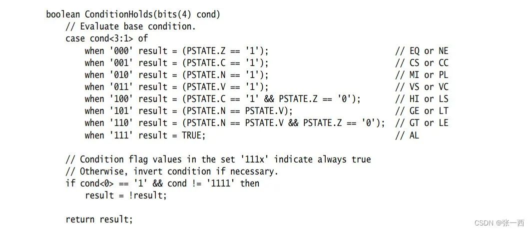
- Derived many branch instructions, for near or function range jumps, such as the following instructions.
- BEQ, BNE jump based on Z==1, BEQ jumps if equal, e.g., CMP X0, X1 BEQ.
- BCS, BCC jump based on C==1, BCS jumps if greater than or equal, BCC jumps if less than.
- BMI, BPL jump based on N==1, BMI jumps if negative, BPL jumps if positive.
- BVS, BVC jump based on V==1, BVS jumps if overflow, BVC jumps if not overflow.
- BHI, BLS jump based on C==1 and Z==0, meaning jump if greater.
- BGE, BLT jump based on N==1 and V==1, or N==0 and V==0 for signed greater than or equal.
- BGT, BLE jump based on Z=0, N==1 and V==1 or Z=0, N==0 and V==0 for signed greater than
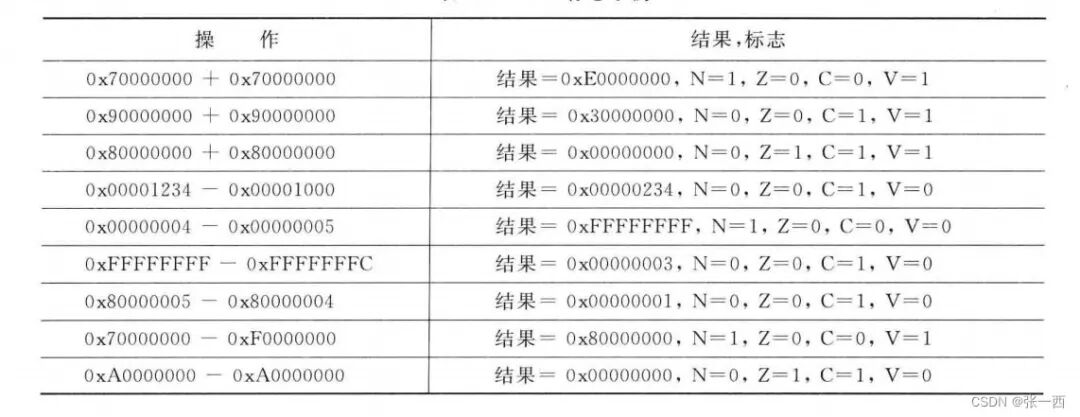
- Related numerical operations affect the flags.
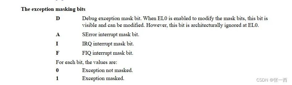
Exception Interrupt Control Field
For example, the common DAIF interrupt mask bits are as follows:
- Processor state debug interrupt mask: watchpoints, breakpoints, and single-step execution.
- System error interrupt mask (usually asynchronous errors).
- Normal interrupt mask.
- Fast interrupt mask
 Common interrupt control fields are shown in the figure above.
 - CortexM3/4 has a separate register primask that can mask interrupts, only normal interrupts, no fast interrupts (supporting nesting, so the fast vs. not fast feels less relevant; also, after entering an interrupt, the hardware automatically pushes the relevant registers to the stack, improving interrupt speed), and there are no interrupt mask-related fields in CPSR.
- CortexR5 and A53 series have such interrupt control fields, which can mask interrupts when accessing critical resources.
Mode Control Field
The low five bits of CPSR are mode control bits, controlling what mode the current CPU is in; setting various modes is to handle exceptions and hierarchical management, where lower levels cannot access specific resources, while privileged modes can perform operations on resources. 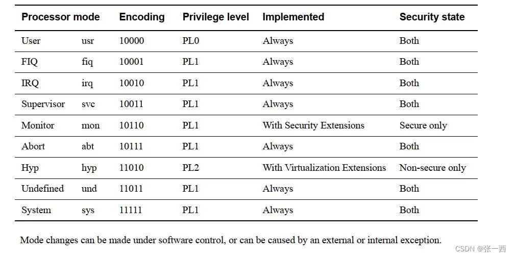
- By writing the low five bits of CPSR, the system can be controlled to be in which mode.
- By reading the fifth bit of CPSR, it can also be known what mode it is currently in, determining what fault has occurred in the program.
| Mode | Description | Restriction |
|---|---|---|
| User Mode | Runs user programs,<span>non-privileged mode</span>, cannot handle exceptions, cannot change the current mode unless an exception occurs. |
Access to system resources is restricted (peripherals and memory). |
| SVC Mode | Used for system management, such as resource access under the system and OS scheduling management, can be triggered by software,<span>privileged mode</span>, executing SVC instruction can enter this exception, after reset, it enters this mode, (<span>normal behavior, triggered by software</span>). |
|
| System Mode | Shares all registers with user mode,<span>privileged mode</span>, cannot enter through exceptions, (<span>normal behavior, triggered by software</span>). |
|
| Abort Mode | Data Abort or Prefetch Abort, the former is a data access error, the latter is an instruction fetch error,<span>privileged mode</span>, (<span>exception behavior, detected by hardware</span>). |
|
| Undefined Mode | Instruction-related exception handling, such as executing an undefined instruction,<span>privileged mode</span>, (<span>exception behavior, detected by hardware</span>). |
|
| FIQ Mode | <span>privileged mode</span>, handles fast interrupts, (<span>normal behavior, triggered by hardware</span>). |
|
| IRQ Mode | <span>privileged mode</span>, handles normal interrupts, (<span>normal behavior, triggered by hardware</span>). |
Instruction Selection Field
| T Value | Instruction Set | Description |
|---|---|---|
| 0 | ARM Instruction Set | 32-bit DWORD aligned instructions |
| 1 | Thumb Instruction Set | Partially 16-bit half-word aligned instructions, increasing code density, reducing image size. |
| X | Associated | Both instruction sets can be mixed, represented by state, e.g., switching instruction sets via bx, blx. |
Endianness Control Field
| Endian State Value | Mode | Description | Setting Instruction |
|---|---|---|---|
| 0 | Little Endian Mode | Memory low byte at low position | SETEND LE |
| 1 | Big Endian Mode | Memory low byte at high position | SETEND BE |
Execution State Control Field
Some control system state flags, such as in the ARMv8-A series.
| Flag Attribute | Description | HTML |
|---|---|---|
| SP_ELx | <span>Stack pointer register selected,</span> |
e.g., SP_EL0 or SP_EL3 |
| EL | <span>Exception Level</span> |
“EL0, EL1, EL2, and EL3” |
| SS | <span>Software Single-Step Control</span> |
for debugger to make PE single-step instruction |
Source: Technology Makes Dreams Greater