
Hardware Installation 1. When supplying power through the USB interface, if the USB data is connected, the APM will cut off the communication function of the data transmission interface. Therefore, please do not use both data transmission and USB cable to debug APM simultaneously. The USB interface has a higher priority than the data transmission interface; only USB cables that provide power are not limited by this rule. 2. The onboard accelerometer of the APM is affected by vibrations, which can produce unnecessary motion deviations that directly affect the flight control attitude calculation. If conditions permit, please try to use a damping platform to install the APM mainboard. 3. The onboard high-precision barometer of the APM is very sensitive to temperature changes, so please try to cover the barometer with a piece of black sponge to block light and avoid the effects of sunlight and thermal radiation in outdoor flying environments. Additionally, covering with sponge can prevent airflow from the aircraft itself from interfering with the barometer.
Usage Recommendations For users using the APM autopilot for the first time, it is recommended to complete the beginner’s usage of the APM step by step: 1. First, install the ground station control software and drivers to familiarize yourself with the various menu functions of the ground station interface; 2. Connect only the USB cable to learn how to download firmware; 3. Connect the receiver and USB cable to complete the remote control calibration, accelerometer calibration, and compass calibration of the APM; 4. Complete the setting of various parameters; 5. Assemble the aircraft and conduct test flights after completing various safety checks; 6. PID parameter adjustments; 7. Various advanced applications of the APM.
Ground Station Debugging Software Mission Planner Installation First, the installation and operation of Mission Planner requires the Microsoft .NET Framework 4.0 component, so please download and install the .NET Framework 4.0 before installing Mission Planner. After installing the .NET Framework, start downloading the Mission Planner installation package. The latest version of Mission Planner can be downloaded by clicking here. Each version on the download page provides both MSI and ZIP versions for selection. The MSI is the application installation package version, which will also install the APM USB driver during the installation process. After installation, you can use it by plugging in the APM’s USB cable. The ZIP version is a portable version that requires no installation; just unzip it to use, but you will need to manually install the APM USB driver after connecting to the APM, and the driver is located in the Driver folder after extraction. Please decide which version to use based on your needs; if this is your first installation, it is recommended to download the MSI version. Taking the MSI version as an example (Note: Please do not connect the APM’s USB cable before installation), double-click the downloaded MSI file, and then click Next step by step. Just continue when the device driver installation wizard pops up, otherwise, the driver installation will be skipped. (I will share various files related to the tutorial on the cloud disk)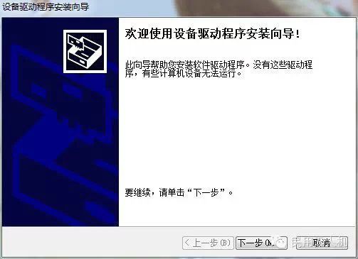 Next, check “Always trust…” and then click Install. The installation program will automatically install the relevant drivers
 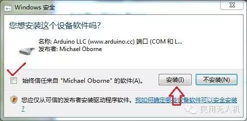 After installing Mission Planner, the installation program generally does not create a shortcut on the desktop, so please open the installation directory yourself, right-click on the ArdupilotMegaPlanner10 file, and select “Send to Desktop” to create a shortcut for future use.
Understanding the Mission Planner Interface After installing Mission Planner and the drivers, you can now start the Mission Planner main program. After starting, the first thing presented is a multifunctional flight data instrument interface. 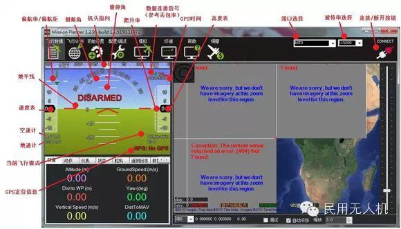 The new version of Mission Planner has localized most of the menus, which is very suitable for the national situation. The main interface has eight main menu buttons in the upper left corner, and the flight data displays real-time flight attitude and data; the flight plan is the task planning menu; initial settings are used for firmware installation and upgrades, as well as some basic settings; configuration debugging includes detailed PID adjustments, parameter adjustments, and other menus; simulation allows the APM to simulate flight on the computer after uploading specific simulator firmware; the terminal is a command-line debugging window similar to a DOS environment, which is very powerful. The upper right corner of the main interface is for port selection, baud rate, and connect/disconnect buttons (connect/disconnect). Specific usage will be explained in subsequent sections.
Firmware Installation The first thing to do after getting the APM is to flash the firmware you need into it. Although the seller may help you flash the firmware before sale, it may not be the firmware that meets your requirements, so learning how to refresh the APM firmware is one of your essential tasks.
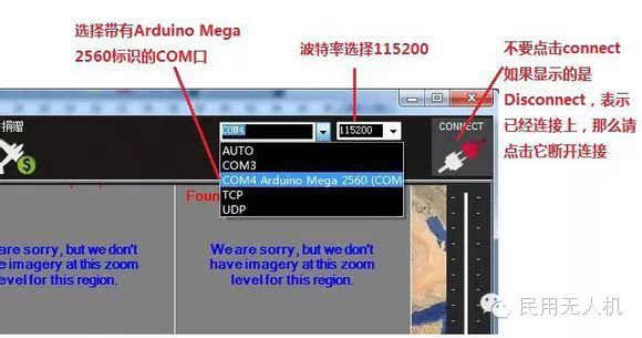
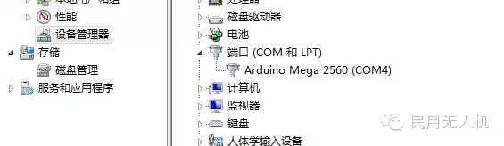 Before installing the firmware, please connect the APM’s USB cable to the computer (others do not need to be connected), ensure that the computer has recognized the APM’s COM port number, then open Mission Planner (hereinafter referred to as MP). In the upper right corner of the MP main interface, select the corresponding COM port from the drop-down box. Generally, the correctly identified COM port will have the Arduino Mega 2560 label; directly select the COM port with this label, and then choose a baud rate of 115200. Note: Please do not click the connect button during the firmware installation process; the program will connect automatically. If you have previously connected the APM, please click Disconnect to disconnect; otherwise, an error message will pop up during the firmware installation process. Also, note: Please do not use wireless data transmission to install firmware, although wireless data transmission has the same communication function as USB, it lacks the reset signal and cannot reset the 2560 during the firmware flashing process, which will lead to installation failure.
Next, click Install setup (initial setup). MP provides two ways to upgrade and install firmware: one is Install Firmware manual mode, and the other is Wizard mode. The Wizard mode will guide you step by step in a dialogue manner to select your corresponding flight control board, flight mode, and other parameters. Although it is more user-friendly, there is a downside: the wizard mode will check your port during the installation process, and due to differences in computer performance, if the port is not effectively released after the check, the subsequent firmware burning will prompt failure, so it is recommended to use the Install Firmware manual mode to install. 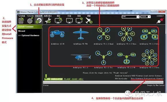 Click Install Firmware, and the window on the right will automatically download the latest firmware from the network and display the firmware name and the corresponding aircraft mode graphically. You only need to click on the image corresponding to your aircraft mode, and MP will automatically download the firmware from the network, then automatically complete the connection to the APM, write the program, verify the program, disconnect, and other series of actions without manual intervention. If you want to use a historical version of the firmware, please click on the bottom right corner Beta firmware pick previous Firmware, and a drop-down box will appear; you just need to select the firmware you need from the drop-down box. Firmware versions after 3.1 will pop up a warning prompt after installation
 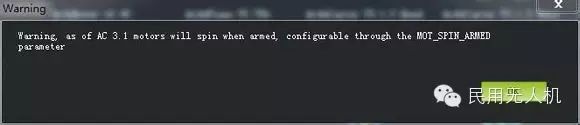 This is to remind you that after unlocking this version of the firmware, the motors will run at idle. If you want to disable or configure this function, please use the MOT_SPIN_ARMED parameter for configuration; please refer to the parameter configuration later for specific usage. After the firmware installation prompt Done is successful, you can click the connect button in the upper right corner to connect to the APM and view the real-time operating attitude and data of the APM. After a brand new firmware is downloaded to the APM board, the first three things you need to do are: first, remote control input calibration; second, accelerometer calibration; third, compass calibration. If these three things are not done, unlocking cannot proceed, and the MP’s attitude interface will continuously pop up a red prompt: PreArm: RC not calibrated (Unlock Preparation: Remote control not calibrated),
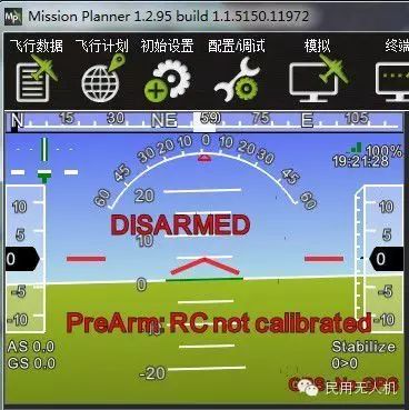
PreArm: INS not calibrated (Accelerometer not calibrated)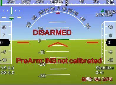 PreArm: Compass not calibrated (Compass not calibrated)
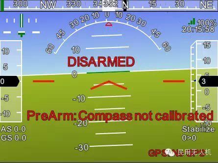
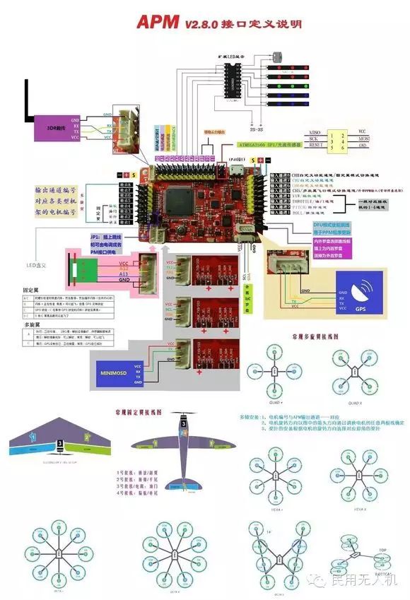
Remote Control Calibration First, perform remote control calibration, which requires connecting your receiver. Please refer to the APM connection installation diagram for specific connections. After connecting, connect the APM’s USB data cable (you can also connect via data transmission), then turn on the power of the remote control transmitter, run MP, select the correct baud rate and port according to the steps in the image below, and click connect to connect to the APM. Then click Install setup (initial setup) -> Mandatory Hardware -> Radio Calibrated (Remote Control Calibration) -> Click the calibration remote button on the right side of the window 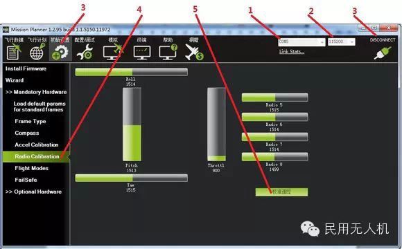
After clicking to calibrate the remote control, two reminders will pop up in sequence: confirm that your remote control transmitter is turned on and the receiver is powered on, and confirm that your motors are not powered (this is very important; during this step, it is recommended that your APM only connect the USB and receiver devices) 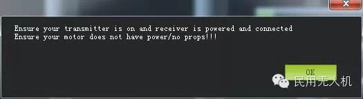 Then click OK to start moving the remote control switches to make the red prompt bars for each channel move to their upper and lower limits
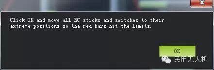
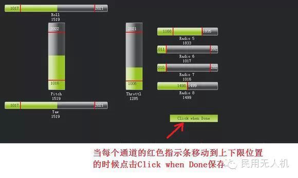 When the red indicator bars for each channel move to their upper and lower limit positions, click Click when Done to save the calibration. After popping up two OK windows, the calibration of the remote control is complete. If the indicator bars do not change when you move the joystick, please check whether the receiver connection is correct, and also check whether each channel corresponds correctly.
Accelerometer Calibration It is recommended to prepare a flat six-sided box or plastic box with neat corners, as shown in the figure below, which will be used as the APM calibration’s horizontal and vertical posture reference. Additionally, a flat table or floor is also needed 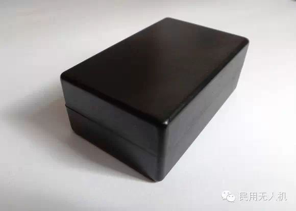
First, use double-sided foam glue or screws to fix the APM mainboard facing up on the square box, as shown in the picture: 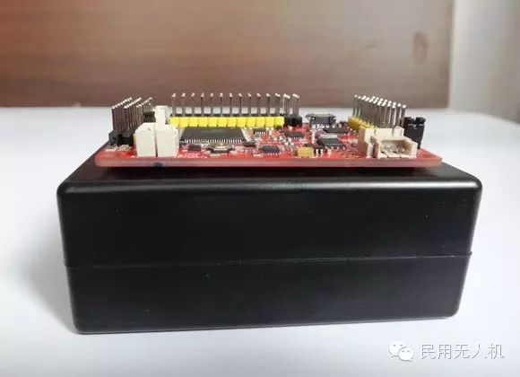 Then connect the APM to the computer, open MP and connect, click Install setup under the Mandatory Hardware menu, select Accel Calibrad (Accelerometer Calibration), and click the right button to start the accelerometer calibration
 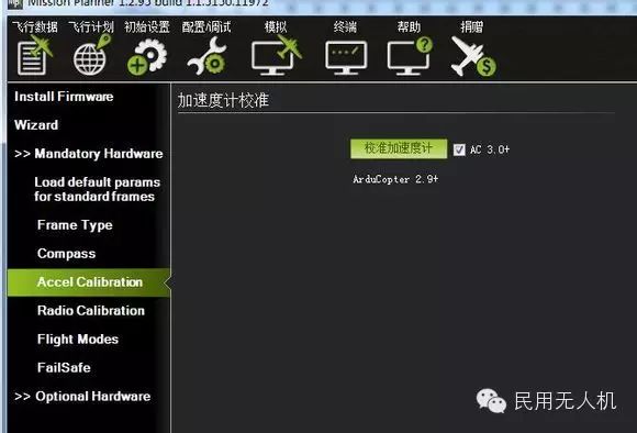 After clicking, a prompt will pop up: Place APM level and press any key (please place the APM horizontally and press any key to continue)
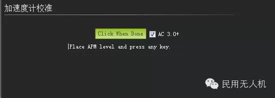 At this time, please place the APM as shown in the figure below, then press any key on the computer keyboard to continue. This is the first action of the accelerometer calibration; the subsequent actions will follow this method
  After completing the first horizontal calibration action, press any key to continue, and the prompt for the second action will appear: Place APM on its LEFT side and press any key (please place the APM vertically with the left side up and press any key to continue)
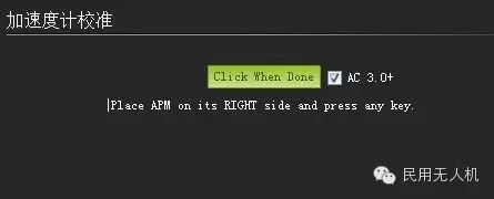
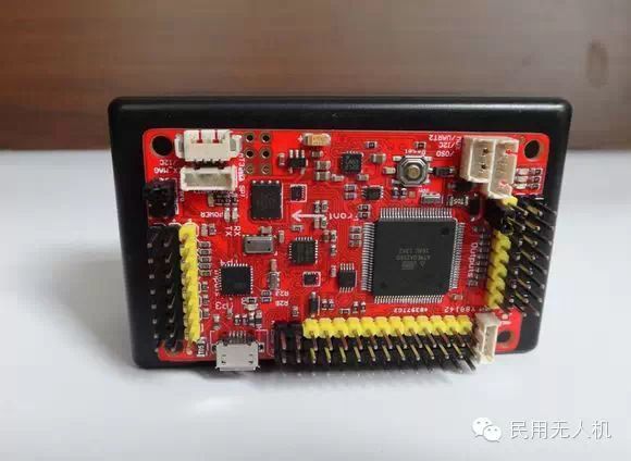
 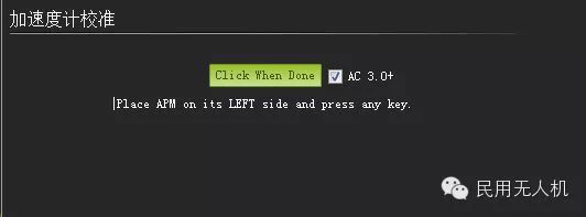 At this time, please place the APM as shown in the figure below, paying attention to the arrow (nose) on the APM board, as the following calibration actions will be based on this to identify the front, back, left, and right of the APM. After placing it correctly, press any key on the computer keyboard to continue
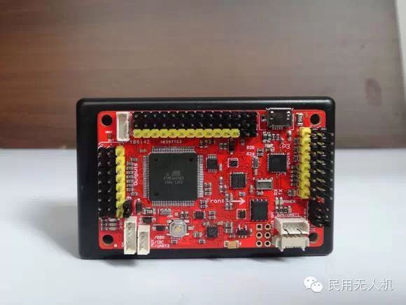
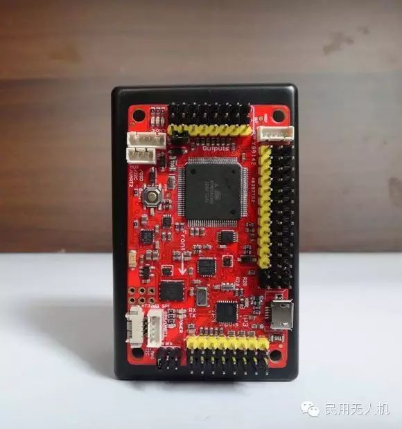
 The fourth action is: Place APM nose DOWN and press any key (please place the APM nose down vertically and press any key to continue)
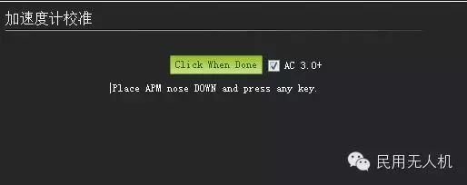
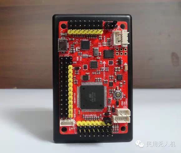
 The fifth action is: Place APM nose UP and press any key (please place the APM nose up vertically and press any key to continue)
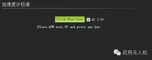
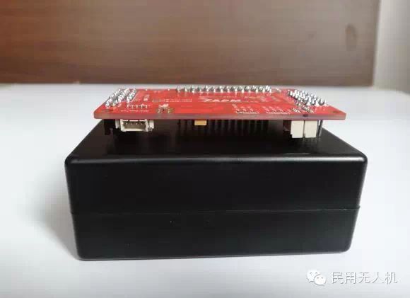
 The last action is: Place APM on its BACK and press any key (please place the APM back up horizontally and press any key to continue)
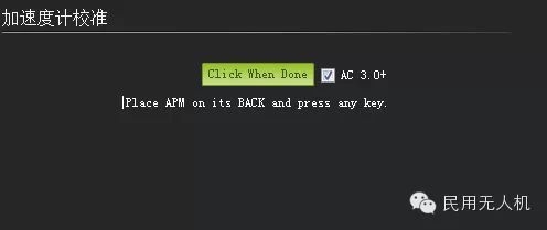
 When Calibration successful appears, congratulations, you can proceed to the next step of compass calibration
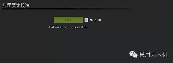
Compass Calibration
The compass calibration page is also under the same menu as the accelerometer calibration. Click Install setup (initial setup) under the Mandatory Hardware menu, select the Compass menu, check the corresponding settings as shown below, and then click Live Calibrad (live calibration) 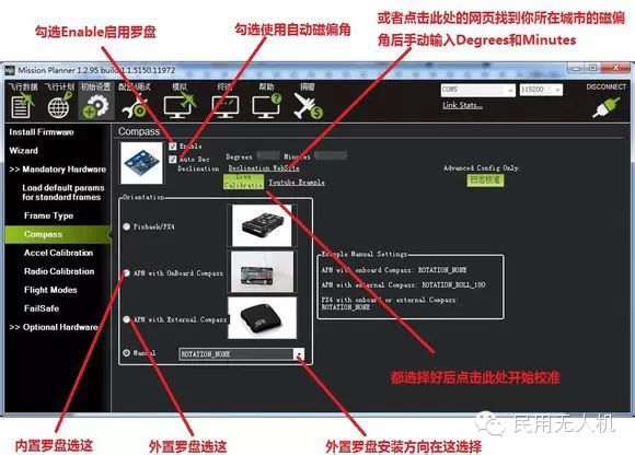 After clicking, a reminder menu will pop up: Please rotate the APM within 60 seconds, rotating each axis at least once, i.e., pitch 360 degrees once, roll 360 degrees once, and rotate horizontally 360 degrees once. If the square box used for the accelerometer calibration is still in place, then place each face facing down once and rotate each face 360 degrees; if it is an external compass, please rotate the external compass
 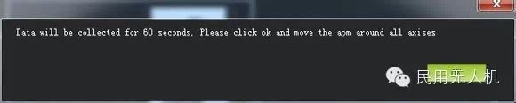 During the rotation, the system will continuously record the data collected by the compass sensor, and the Samples data will continue to accumulate. If the Samples data does not change, please check whether your compass has been correctly connected. After 60 seconds, a data confirmation menu will pop up; click OK to save and complete the compass calibration
 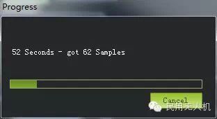 Regarding the choice of external compass: If you are using an external compass, you first need to disable the built-in compass. For the V2.5.2 version APM, the method to disable the built-in compass is to disconnect a preset solder pad next to the compass chip. For the V2.8.0 version APM, you only need to remove the jumper cap marked MAG on the board. During the calibration process, if your external compass is installed with the chip characters facing down, you need to select Rotation_Roll_180 in the Rotation drop-down box, which means the compass chip is installed with a roll of 180 degrees, keeping the nose direction unchanged. If you want to customize the heading direction of the external compass, for example, you can choose Rotation_Yaw_45 (nose deflected 45 degrees), Rotation_Pitch_180 (pitch flipped 180 degrees, swapping nose and tail), and other choices can be deduced accordingly. Supplement (I cannot demonstrate compass calibration here, but I recommend using Teacher Bubble’s compass calibration video)
Flight Mode Configuration In actual flight, the APM’s function switching is achieved through switching flight modes. The APM has multiple flight modes to choose from, but generally, only six can be set at a time, plus CH7 and CH8 auxiliary modes, for a maximum of eight modes. Therefore, one of your remote control channels needs to support switching six segment PWM value output, generally using the fifth channel as the mode switching control channel (the eighth channel for fixed-wing aircraft). When the PWM value input of the fifth channel is in the ranges of 0-1230, 1231-1360, 1361-1490, 1491-1620, 1621-1749, 1750+, each range can activate a corresponding flight mode. The recommended six PWM values are 1165, 1295, 1425, 1555, 1685, 1815nS. If your remote control has this function, congratulations, you can configure your APM flight modes according to the following text. If it does not have this function, it is recommended to refer to the article in the appendix of this manual about modifying the remote control to output six segments; otherwise, you might only be able to configure 3 or even 2 flight modes. Before configuring the flight modes, you also need to connect MP to APM, click Config/Tuning (configuration debugging) menu, and select Flight Modes, which will pop up the following flight mode configuration interface: 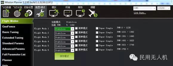 In the configuration interface, the PWM values corresponding to the six flight modes, whether to enable simple mode and super simple mode are all clear at a glance. The mode selection can be made by choosing from the drop-down box. For safety reasons, it is generally recommended to set 0-1230 to RTL (return to home mode). The other five can be configured according to your remote control habits, but one principle is to ensure that your mode switching switch can always switch to Stabilize (self-stabilizing) mode. After selecting the six modes, please click save mode to save.
Next is the fail-safe protection of APM~ The fail-safe protection of APM is configured through the FailSafe menu: 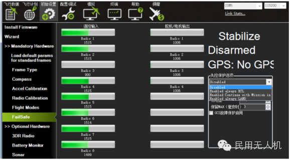 The conditions for triggering APM’s fail-safe protection include throttle PWM, battery voltage (requires current meter), etc. When the trigger conditions are met, for example, if the throttle PWM value is below the set value, the fail-safe protection options can be activated. The fail-safe protection options include RTL (return to home), continue mission, LAND (landing), etc. Generally, it is not recommended to use APM’s own fail-safe protection function, as APM’s fail-safe protection is based on the MCU’s real-time operation. Adding a fail-safe protection means adding an IF operating condition to the MCU’s real-time operation. When the fail-safe trigger condition is in a critical non-steady state, the repeated triggering of the IF may affect the MCU’s operation and cause the aircraft to crash. Therefore, if you want to use the fail-safe protection function, it is recommended to use the fail-safe protection function provided by the remote control, such as setting the remote control receiver to switch to return-to-home mode or landing mode when the remote control signal is lost, while maintaining the throttle channel at the value before losing control.
Regarding ~ fail-safe protection, I will insert Teacher Bubble’s video.
Using the Command Line Since the use of commands was not mentioned in Teacher Bubble’s video, I will briefly explain that the TERMINAL in the MP ground station is a serial debugging tool similar to a DOS environment. Through it, you can test the raw output data stream of sensors, configure APM’s functions, clear configuration information, set download logs, and browse logs. It can be said that the function is very powerful. Below is an example of viewing the output data of the gyroscope to illustrate the use of the TERMINAL; other functions can be explored on your own. Once connected APM to the computer, open MP, select the correct port and baud rate, then click on the TERMINAL (terminal) menu, and click the Connect button in the upper left corner of the interface, note: not the total connect button in the upper right corner 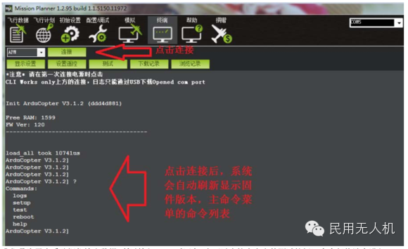 We want to check the gyroscope output data, so type test and press Enter (you can also directly click the test button above), and the command line terminal will enter the test secondary menu
 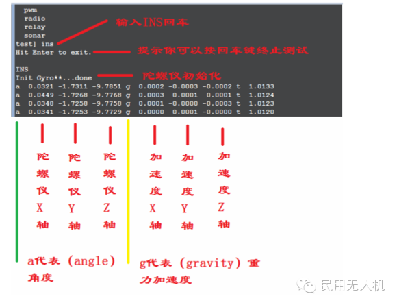 In the secondary test menu, we can type help or ? to view the available commands under the test menu
 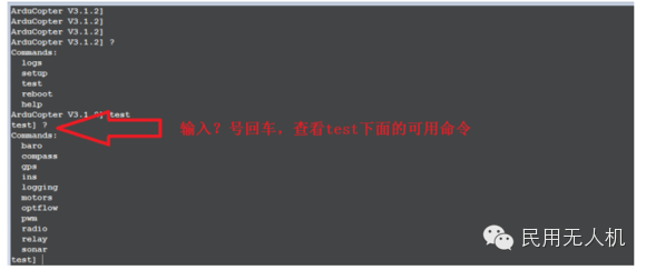 You can see that the test menu includes various test commands such as baro barometer, compass, GPS, INS gyroscope, logging, motors, etc. We want to see the gyroscope, so type ins and press Enter, and we will see the following information
  Through the above data, we can clearly see the output status of the gyroscope. To terminate the output, press Enter, and use the exit command to return to the previous menu. Other commands can be deduced accordingly. One important point is that in the setup menu, you can use the erase command to erase the configuration information of the EEPROM, which is a commonly used command.
APM Flight Mode Annotations 1. Stabilize Mode: The most commonly used flight mode, as well as the most basic flight mode, should be used for takeoff and landing. In this mode, the flight control will keep the aircraft stable, making it the first choice for beginners and the best mode for FPV first-person flight. Be sure to ensure that the switch on the remote control can easily and accurately switch to this mode, which will be very important in emergencies. 2. Acro Mode: This is a non-stabilized mode; the APM will rely entirely on the control of the remote control, which is not recommended for beginners. 3. Alt Hold Mode: The altitude hold mode (Alt Hold) uses automatic throttle to attempt to maintain the current height in a stable mode. In altitude hold mode, height can still be controlled by increasing or decreasing throttle, but there will be a throttle dead zone in between. The aircraft will only respond to your ascent and descent actions when the throttle action exceeds this dead zone. When entering any mode with automatic altitude control, your current throttle will be used as a reference to maintain altitude. Be sure to ensure that you are hovering at a stable height before entering the altitude hold. The aircraft will compensate for poor values over time. As long as it does not drop too quickly, there will be no problem. Please be careful when leaving the altitude hold mode; the throttle position will become the new throttle, and if it is not in the neutral hover position of the aircraft, it will cause the aircraft to drop or rise rapidly. In this mode, you cannot land or shut down the motors because the throttle stick now controls altitude, not the motors. Please switch to stabilize mode to land and shut down the motors. 4. Loiter Mode: The loiter mode is a GPS point + altitude hold mode. You should let the GPS point before takeoff to avoid sudden positioning issues in the air. Other aspects are basically the same as the altitude hold mode, except that horizontal positioning is done by GPS. 5. Simple Mode: The simple mode is equivalent to a headless mode; there is a Simple Mode checkbox next to each flight mode that can be checked. After checking the simple mode, the aircraft will unlock the nose direction before takeoff as the direction of the remote control forward stick, so you do not have to worry about the aircraft’s attitude, which is very useful for beginners.
6. Auto Mode: In auto mode, the aircraft will control its flight according to pre-set mission planning. Since mission planning relies on GPS positioning information, it is necessary to ensure that GPS has completed positioning (the blue LED on the APM board is always on) before unlocking and taking off. There are two situations for switching to auto mode: if using auto mode to take off from the ground, the aircraft has a safety mechanism to prevent you from mistakenly switching to auto mode and causing danger, so you need to manually unlock and manually push the throttle to take off. After takeoff, the aircraft will reference the throttle value from the last ALT Hold altitude as the throttle benchmark. When climbing to the first target height of the mission planning, it will begin executing the mission to fly to the target; if switching to auto mode in the air, the aircraft will first climb to the height of the first target and then begin executing the mission. 7. RTL Mode: The return-to-home mode requires GPS positioning. The GPS positioning point before each unlock is the current “home” position; if the GPS is not positioned before takeoff, the first positioning point in the air will become “home”. After entering RTL mode, the aircraft will ascend to 15 meters, or if it is already above 15 meters, it will maintain its current height and then return to “home”. It can also set advanced parameters to choose whether to land autonomously after reaching “home” and how many seconds to hover before landing autonomously. 8. Circle Mode: When entering circle mode, the aircraft will fly in a circle around the current position as the center. At this time, the nose will not be controlled by the remote control direction; it will always point to the center. If the remote control issues commands in the roll and pitch directions, it will move the center. Similar to altitude hold mode, height can be adjusted through throttle, but landing is not possible. The radius of the circle can be adjusted through advanced parameter settings. 9. Guided Mode: This mode requires communication between the ground station software and the aircraft. After connecting, you can right-click on any position on the map interface in the Mission Planner software and select “Fly to here” from the pop-up menu. The software will prompt you to enter a height, and the aircraft will fly to the specified position and height and maintain a hover. 10. Follow Me Mode: The basic principle of the Follow Me mode is that the operator’s laptop has GPS, and this GPS will continuously send location information to the aircraft through the ground station and data transmission radio, and the aircraft will actually execute the “fly to here” command. The result is that the aircraft follows the operator’s movement.
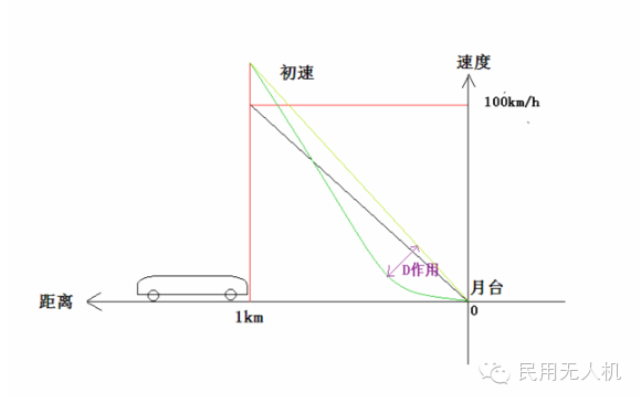
APM PID Tuning Simplified Understanding In the APM parameter settings menu, there is a PID setting. For those who have not come into contact with PID, it can be completely confusing, a bunch of incomprehensible numbers. In view of this, this article strives to explain the various meanings of PID in simple language. PID control is a widely used control method in the field of automation control. P represents Proportional, I represents Integral, and D represents Derivative. From these terms, it can be seen that PID control is based on an important branch of mathematics: calculus, which is a digital automatic control method based on sensor data as input, calculates according to preset PID parameters based on specific formulas, and outputs control. To give a vivid example: a train approaching a station will cut off power when it is about to arrive, allowing it to glide to the platform position based on inertia. If the train is set to cut off power at a speed of 100km/h when it is 1km away from the station, then this 100 compared to 1 represents the meaning of Proportional P. The larger the P value, the faster it starts gliding before reaching the station. The benefit of a faster initial gliding speed is that it arrives at the station quickly, but if the initial gliding speed is too fast, the train will overshoot the platform due to inertia, forcing it to backtrack. However, if P is set too large, the backtracking will also cause the train to overshoot again, thus creating a situation of repeated forward and backward oscillation. If P is set too small, the arrival speed will become very slow, extending the arrival time. Therefore, setting an appropriate P value is the primary task of PID adjustment. Since P is a fixed value, if we idealize the relationship between the train’s speed and the platform’s distance using a coordinate graph, not considering inertia and external forces, the relationship between the two will show that the adjustment of P will result in a straight diagonal line; the steeper the line, the shorter the arrival time 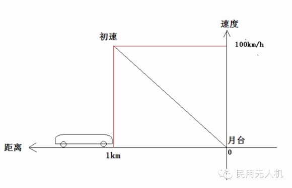 The result of P adjustment in the above figure is only for understanding convenience; in practice, this is impossible to occur, and the result of PID calculation is not like this. In any case, if there is only P adjustment, the train will either set a relatively low P value to reach the target platform very slowly or overshoot, making it difficult to achieve a balance between speed and accuracy. Therefore, the next step is to explain the role of D, the derivative. Based on the example above, if P equals 100, the train can just glide to the platform, and the time spent is 10 minutes. However, for an automation system with very high self-stabilization performance requirements, this 10 minutes is too long. Can it be faster? Yes, we can increase P to 120 and have the train driver operate the train at 120km/h to start decelerating when it is 1km away from the station. Then, when it is 500 meters away, step on the brakes to reduce the speed to 80km/h, then at 300 meters, step on the brakes again to reduce the speed to 50km/h, and at 100 meters, step on the brakes to reduce the speed to 20km/h, allowing the train to accurately arrive at the platform in a shorter time. This is the role of D; we can think of D as braking. If we still use a coordinate graph to illustrate the effect of D on P adjustment, D turns the straight line produced by P adjustment into a curve. In the PID formula, D’s left and right change the curve produced by P; the larger the D value, the more significant the effect on P. After adding D, the curve is steep at first, leading to a fast arrival and flatter later, allowing the train to arrive at the station smoothly and accurately.
 I believe that after this explanation, many model friends will understand the role of PD. Therefore, in the actual tuning of the aircraft, we can have targeted adjustments. Based on the relationship of PD, we can derive a tuning step: first set D to zero, increase P value, causing the aircraft to overshoot and start oscillating, then increase D’s value, lowering P to adjust the later effect, and finally adjusting until there is no overshooting. The larger the P, the faster the aircraft recovers after tilting, which is reflected in being more sensitive, but too large will produce oscillation; the larger the D, the smoother the adjustment, which is reflected in being more stable, but if D is too large, it will prolong the adjustment time, resulting in a sluggish response (the D here refers to the value of D; in general PID representation, the closer D is to 0, the more significant P’s effect, which needs to be noted). Finally, let’s explain the role of I, the integral. I is added to eliminate errors. If in the previous example, the train stops after reaching the station but is still 1 meter away from the final target stop line, we can consider this as a qualified stop, but this is still an error. If we accept this 1-meter error, the next time the train approaches the station, there will be a 2-meter error. This will continue, and the error will increasingly grow. Therefore, we need to record this error, so when the train approaches a second time, it can play a role. If it is 1 meter away, the train driver can adjust by delaying 1 meter output (or ahead), that is to start decelerating at 999 meters, ultimately arriving precisely at the stop line. Without the effect of I, the performance on multi-rotor platforms would be that the aircraft tilts more and more, eventually losing balance. The adjustment of I is based on PD, so any changes in PD will affect the effect of I. Therefore, the final adjustment steps are to first adjust P to establish sensitivity, then adjust D to stabilize, and finally adjust I to determine accuracy.
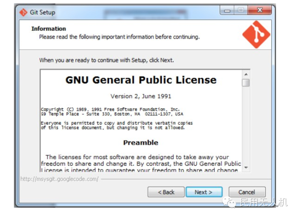
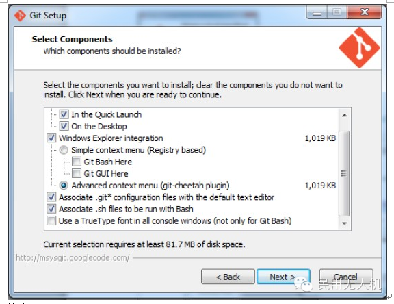
Next, let’s talk about compiling Arduino and downloading the latest firmware The first step is to install GIT. Please follow the steps in the picture below to download and install step by step 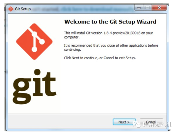
According to the summary of common faults from Cold Wind, let’s talk about common fault handling. In the new version of MP, there is a visual sphere for compass calibration to indicate the rotation situation. However, sometimes the original compass calibration data may have excessive errors, leading to the sphere data points not being able to fill the entire sphere during recalibration, and the compass direction can only change within a certain range of degrees, unable to point correctly in 360 degrees. The solution is to first restore the compass calibration data and then recalibrate. The restoration method: go to the Full Parameter List parameter list, find COMPASS_OFS_X, COMPASS_OFS_Y, COMPASS_OFS_Z, and set these three parameters to 0, then click write parameters to save. 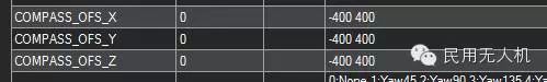
Fault Two: Motor output does not rise after unlocking. This fault is caused by saving incorrect remote control calibration parameters, requiring recalibration of the remote control. However, sometimes even after recalibrating the remote control, the fault persists. In this case, you need to manually restore the remote control calibration data before recalibrating. The restoration method is to go to the Full Parameter List parameter list, find RC1_MAX, RC1_MIN, RC1_TRIM for each channel, including RC2, RC3, etc., where MAX is the maximum value (default 1900), MIN is the minimum value (default 1100), and TRIM is the middle value (default 1500). Many times, the motor output not rising is because the TRIM middle value has been calibrated and saved near the low point of 1100, causing the motor speed not to rise even when the throttle is fully engaged. Just change these three values for each channel back to default, then write parameters and recalibrate the remote control. Sometimes if parameters cannot be written, execute the reset command in the terminal or flash the car and then flash it back to the aircraft to solve the issue. 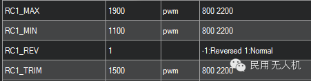
This article is authored by: Cold Wind Group Leader
We update drone news and useful information every day!
Long press the QR code to follow us!