Abstract: This paper designs an intelligent warehouse item sorting robot that can adapt to various terrains. The robot’s structure consists of a shock-absorbing operating system, a six-degree-of-freedom robotic arm, and a mechanical gripper; the control system is composed of a QR code, Arduino, tracking module, servo control module, motor drive module, ultrasonic module, servos, and a reduction motor. This robot can transport and sort items on various terrains, with low cost, high precision, and good stability, making it practically valuable.
Keywords: All-terrain; Transport; Warehouse; Robot; Arduino; Design
Introduction
In recent years, labor costs have been continuously rising, and the phenomenon of “machines replacing humans” has emerged in various fields, particularly in the industrial sector, where the transformation of industrial robots towards intelligent manufacturing is gaining strong momentum and broad prospects[1,2]. Industrial robots have significantly boosted productivity in manufacturing, leading to an increasingly large inventory of goods, while the urgent need for rapid, orderly, and accurate storage and sorting solutions has made intelligent warehouse item sorting robots a focal point. Additionally, during the COVID-19 pandemic, cases of “the separation of live COVID-19 virus from the outer packaging of cold chain food”[3] were discovered, raising concerns for the health and safety of workers. Therefore, the processes of logistics reception, sorting, and organization need to be fully automated by robots until all items have been thoroughly disinfected, ensuring safety before human intervention. Thus, robots for sorting and organizing warehouse items have become a significant focus.
Currently, warehouse item sorting robots are mainly divided into two types: one has a flexible robotic arm but is fixed in position, cannot move, lacks intelligent control, and does not have visual recognition capabilities; the operation is purely mechanical. The other type is an intelligent robot that can freely move and transport items, but it cannot function properly in complex terrains and lacks grasping capabilities, relying solely on other auxiliary devices to complete warehouse organization. In many industries, especially logistics, the transportation and organization of goods are still primarily done manually, failing to meet the rapidly evolving market demands, resulting in low transport efficiency and high costs. Furthermore, it does not satisfy the requirements for epidemic prevention and control, leaving workers’ health and safety uncontrollable. Market validation has shown that replacing human labor with robots can meet epidemic prevention requirements and improve production efficiency, ultimately reducing costs in the long run[4,5]. Given that logistics transportation environments are often complex, current transport and organization robots are generally used in favorable conditions, failing to meet the emerging logistics industry’s needs, such as the material handling robots from Passion Mobility and Alibaba’s Cao Cao AGV robots. Therefore, to address the issues of transport robots being unable to adapt to rugged terrains, high costs, and operational difficulties, this paper designs a low-cost, easy-to-operate all-terrain intelligent warehouse item sorting robot that can transport goods and adapt to various terrains, thereby improving the production efficiency and economic benefits of industries with high transport and organization demands like logistics.
1 Structure System Design
1.1 Design of the Operating System
As the complexity of the operating environment increases, the performance requirements for the all-terrain intelligent warehouse item sorting robot also rise, yet there are still issues with vehicle stability during steering[6]. To address this, some methods have been proposed to improve the robot’s operational vibration issues, such as using pre-programmed intelligent algorithms to control the vehicle’s motion posture, thereby reducing the degree of vibration[7]. By designing different types of walking components, the adherence of the walking components to the ground can be improved, which in turn improves the vehicle’s vibration state[8]. However, for more complex transport and sorting locations, these methods cannot fully resolve the vibration’s impact on the robot’s operational stability. To achieve transportation and other functions under various terrain conditions, the reliable operation of the all-terrain intelligent warehouse item sorting robot is a necessary condition for ensuring that the above tasks can be completed smoothly, and the stability of the vehicle’s motion is an important prerequisite for its reliable operation[9,10], thus research on improving vehicle motion stability is of significant importance.
Vehicle motion stability refers to the minimal vibration of the robot while operating on complex terrains, ensuring that items are delivered accurately to designated locations. The minimal vibration is primarily achieved through shock absorbers in the operating system, and this paper proposes a new design tailored to these needs. As shown in Figure 1, the operating system consists of the operating vehicle body, shock absorbers, tracks, driving wheels, load-bearing wheels, and guiding wheels. The operating vehicle body serves as the frame, connecting and securing all components except the tracks, which envelop all components except the vehicle body.
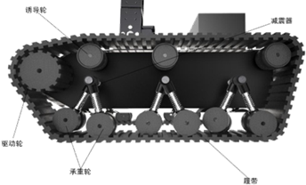
Figure 1 Structure Diagram of the Operating System
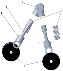
As shown in Figure 2, the shock absorber consists of springs, connecting shafts, hydraulic columns, connectors, and load-bearing wheels, where the hydraulic column is the main cushioning component. When the track is under load, the force is transmitted to the spring and hydraulic column through the load-bearing wheel; the spring is compressed under this force, subsequently exerting an equal force in the opposite direction. Once the spring reaches a certain level of compression, the force is transferred to the hydraulic column, which begins to buffer the impact. Once all pressure is buffered, the spring and hydraulic column return to their original state, achieving the shock absorption effect and stabilizing the robot. The connecting shaft secures the shock absorber to the operating vehicle body, while the connector links the load-bearing wheel and the connecting shaft. The load-bearing wheel not only supports the overall weight of the robot but also acts as a driven wheel for the shock absorber, providing strong stability. The guiding wheel is used to guide and support the track and is also a driven wheel, working alongside the track tensioner to adjust the track’s tightness while fixing the upper track to prevent collapse during use. The driving wheel is rotated by a high-speed motor, ensuring the robot operates normally with strong efficiency, reliable work, and low maintenance costs.
-
1. Spring 2. Connecting Shaft 3. Hydraulic Column 4. Connector 5. Load-Bearing Wheel
Figure 2 Structural Diagram of the Shock Absorber
1.2 Design of the Six-Degree-of-Freedom Robotic Arm
The robotic arm is the most important tool for the transport robot to achieve its sorting goals, ensuring the integrity of transported items and the accuracy of their placement. Therefore, the robotic arm must have appropriate degrees of freedom while ensuring sufficient rigidity and strength, and its extension and rotation must be accurate and efficient[11]. The stability, flexibility, and safety of the robotic arm are crucial guarantees for whether a robot can efficiently and stably complete its tasks.
As shown in Figure 3, the structure of the robotic arm consists of a 42BYG34-401A stepper motor, a transmission plate, and a rotating base. The 42BYG34-401A stepper motor is the power source for the entire robotic arm, with the transmission plate attached beside the stepper motor, moving along with it, with an angle range of 27° to 136°, enabling the entire robotic arm to move forward and backward, rotate around the X and Z axes, and move along the X and Y axes, allowing it to execute commands accurately and efficiently. The rotating base is equipped with a constant-speed motor, enabling rotation around the Z axis.
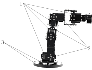
1. 42BYG34-401A Stepper Motor 2. Transmission Plate 3. Rotating Base
Figure 3 Structure of the Robotic Arm
As shown in Figure 4, the driving unit of the robotic arm is the main component of the robotic arm’s motion, with the entire robotic arm relying on this structure to perform its movements. The connecting plate is fixedly connected to the stepper motor, facilitating the connection of the driving structure and ensuring safety and stability. The stepper motor serves as the power source for the driving structure, ensuring the normal operation of the entire robotic arm. The stepper motor is controlled by pulse signals, with its rotor rotating a certain angle in response to changes in the pulse signals, thereby accurately adjusting the motion of the entire driving structure. The driven plate is connected to the stepper motor via a coupling on one side, while the other side connects to the next driving structure, changing with the rotation angle of the stepper motor. The selected 42BYG34-401A stepper motor has a step angle of 3° to 5°. The rigid coupling connects to the rotor of the stepper motor to drive the driven plate; its simple structure, low cost, reliable work, and ability to transmit substantial torque ensure high alignment precision between the two axes, commonly used in stable load, high-speed, or high-precision transmission systems.
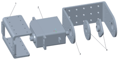
1. Connecting Plate 2. Stepper Motor 3. Driven Plate 4. Rigid Coupling
Figure 4 Driving Unit Diagram
1.3 Design of the Mechanical Gripper
As shown in Figure 5, the power source for the robotic arm’s hand is driven by a stepper motor that moves the active gear, which in turn drives two passive gears. These two passive gears are connected to two rods of the gripper, which move the other parts of the gripper. When the driving active gear rotates clockwise, the gripper contracts to grasp an object; when the active gear rotates counterclockwise, the gripper relaxes to release the object. Depending on the size of the item, commands are sent via pulse signals to control the amount of contraction and relaxation of the gripper.
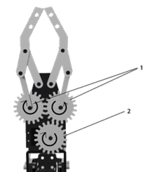
1. Passive Gear 2. Active Gear
Figure 5 Structure Diagram of the Mechanical Gripper
1.4 Overall Structure System
As shown in Figure 6, the all-terrain intelligent warehouse item sorting robot mainly consists of a multi-degree-of-freedom flexible robotic hand, a QR code color recognition camera module (1080p), and a self-designed innovative track-type shock-absorbing chassis. In actual work, the robot receives and sends information and commands through a control center to operate the robot body according to specific task requirements. First, the control program is prepared, and the robot is started without contact. The camera on top of the robotic arm captures information and feeds it back to the control center, which issues commands to drive the four stepper motors on the robotic arm, adjusting the direction and angle of the mechanical gripper, while the motor in the arm’s transmission plate drives the gears to execute the gripper’s grasping action. During the grasping process, the top camera identifies the gripper’s grasping status, and once the grasping task is completed, feedback is sent to the Raspberry Pi control board. The control center sends commands to the stepper motors on the chassis, driving the track’s active wheels to move or stop. During movement, the active wheels adjust speed based on commands to achieve straight movement or steering, thereby enabling the transport of objects. During transport, the infrared distance sensor detects obstacles and feeds back to the control center, which sends commands to the stepper motors on the chassis to obtain a reasonable steering angle to avoid obstacles. Upon reaching the designated location, the top camera identifies the specified area, sends feedback to the Raspberry Pi control board, and the control center sends commands to the stepper motors on the robotic arm to adjust the direction and angle, enabling the gripper to place the item. After completing the task, all parts of the robot return to their initial or designated positions automatically according to the program instructions.
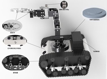
Figure 6 Overall Structure Diagram
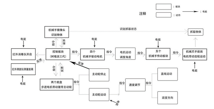
2 Control System Design
The control system of the all-terrain intelligent warehouse item sorting robot consists of a QR code, Raspberry Pi, Arduino, tracking module, servo control module, motor drive module, ultrasonic module, servos, and reduction motors. As shown in Figure 7, the camera communicates with the Arduino through the Raspberry Pi’s serial port to achieve material color recognition and QR code recognition. The tracking module and ultrasonic module transmit signals to the Arduino, which controls the forward and backward rotation and stopping of the motors to manage the sorting robot’s turning, reversing, moving forward, and stopping, as well as controlling the servos’ forward or reverse rotation to manage the opening and closing of the robotic arm’s gripper.
1) QR Code Recognition: QR code recognition converts the graphic of the QR code into usable information through devices. If we were to recognize it based on the programming principles of barcodes, the work would be too cumbersome, as every programmer would have to understand the principles of each barcode, which is inconvenient in practice. This design adopts a barcode recognition toolkit combined with the Raspberry Pi Linux platform to implement QR code recognition. The advantage of this toolkit is that it simplifies programming without needing to master various barcode encoding rules, while achieving a high recognition rate.
2) Color Recognition: Digital images generally use RGB, CMYK, and HSV modes. RGB and CMYK color modes are widely used in video cameras, digital images, and digital videos, but the HSV model better aligns with human descriptions and interpretations of color (H for hue, S for saturation, V for brightness). Therefore, we choose to recognize the material’s RGB values and convert them to HSV mode for color recognition.
3 Experimental Analysis
A prototype was produced based on the design scheme, and related testing experiments were conducted. The prototype was tested for QR code recognition, camera color recognition, operation on complex terrains, and item transport and sorting to verify the feasibility of the design scheme.
1) QR Code Recognition Function: The operation is stable, with a recognition rate of 100%;
2) Camera Color Recognition Function: The operation is stable, with accuracy meeting expectations; the errors were analyzed and found not to be hardware issues, but rather that the recognition algorithm’s precision requires improvement;
3) Operation on Complex Terrains: The operation is good, with decent adaptability to various terrains, stability meeting basic requirements, and room for improvement;
4) Item Transport and Sorting: The operation is good, essentially completing task requirements, but efficiency is somewhat low.
Conclusion
The structure of the all-terrain intelligent warehouse item sorting robot mainly comprises an all-terrain shock-absorbing system, a robotic arm, and a mechanical gripper, enabling it to perform transport tasks normally across various terrains. After prototype testing, this robot has demonstrated stable operation on various terrains, with advantages of good stability, simple operation, high intelligence, and low cost. In the future, it will have good application prospects in sectors such as agriculture, mining, and logistics.
References
[1] Huang Zhenyuan, Yang Zhichao, Feng Yuan, et al. Software Design and Experiment of Industrial Transport Robot Control System[J]. Industrial Control Computer, 2021, 34(11): 77, 78, 80.
[2] Liu Bin. Research on the Motion Control System of Industrial Transport Robots Based on PLC[D]. Tangshan: North China University of Science and Technology, 2020.
[3] Wang Chongmin. Live COVID-19 Virus Detected from Outer Packaging of Cold Chain Food by the Chinese Center for Disease Control and Prevention[J]. Food Safety Guide, 2020(31): 14.
[4] Ren Fang. New Intelligent Warehouse Robots and Their Applications[J]. Logistics Technology and Applications, 2018, 23(8): 80-83.
[5] Yang Yiheng. Research and Development of Control Systems for Six-Joint Transport Robots[D]. Guangzhou: Guangdong University of Technology, 2021.
[6] Shen Dengchao. Analysis of the Dynamic Characteristics and Steering Control Strategies of All-Terrain Mobile Robot Vibration Systems[D]. Hefei: Anhui University of Engineering, 2020.
[7] Jiao Xin. Simulation Research on the Dynamic Characteristics of Vehicle Shock Absorbers[D]. Chengdu: Southwest Jiaotong University, 2014.
[8] Zheng J, Liu Z, Gao H, et al. A Novel Active Deform and Wheel-Legged Suspension of Mars Rover[C]//IEEE International Conference on Robotics & Biomimetics, IEEE, 2017: 7-12.
[9] Wang Chaoxing. Design of Mechanical Structure and Control System of All-Terrain Mobile Robot[D]. Beijing: Beijing University of Chemical Technology, 2017.
[10] Li Chao, Deng Xiaobao, Shi Yuntao, et al. Design of an Experimental Platform for Intelligent Transport Robots in Industrial Wireless Networks[J]. Laboratory Research and Exploration, 2019, 38(12): 79-82.
[11] Gao Sheng, Li Zheng, Zhang Wei. Automatic Modeling and Three-Dimensional Navigation Planning of Robotic Arms[J]. Computer Simulation, 2020, 37(10): 6.
