Source: Embedded Development Notes
Introduction:This article is a hands-on tutorial on ADC sampling and various filtering algorithms. The MCU used in this tutorial is STM32F103ZET6. The teaching is based on the ADC sampling functions of the HAL library, analyzing and comparing the experimental results of various common filters, and visually demonstrating the filtering effects with the VOFA+ tool.
Experimental Effect Diagram:
1. ADC Sampling
1.1 Introduction to ADC
The microcontroller is a digital chip that only recognizes logical sequences composed of 0s and 1s. However, in reality, there are many analog physical quantities in life that are not just 0 and 1, such as temperature and humidity. In such cases, AD conversion is often required, where AD stands for Analog to Digital, converting analog quantities into digital quantities; conversely, DA stands for Digital to Analog, converting digital quantities back into analog quantities.
ADC, short for Analog to Digital Converter, is a device that converts external analog signals into digital signals. Using it to read values from the IO port will no longer yield simple 0s or 1s, but rather continuously variable values. ADC sampling is the process of converting continuously changing analog quantities over time into discretely sampled values.
Several important parameters of ADC:<br/>(1) Measurement Range: The measurement range for an ADC is like the range of a ruler; it determines the output voltage range of the connected device's signal, which must not exceed the ADC's measurement range (for example, the ADC of the STM32 series should not exceed 3.3V).<br/>(2) Resolution: If the ADC's measurement range is 0-5V and the resolution is set to 12 bits, the smallest voltage we can measure is 5V divided by 2 raised to the power of 12, which is 5/4096=0.00122V. Clearly, the higher the resolution, the more accurate the collected signal, making resolution an important metric for evaluating ADC performance.<br/>(3) Sampling Time: When the ADC samples the external voltage signal at a certain moment, the external signal should remain unchanged. However, in reality, the external signal is constantly changing. Therefore, there is a hold circuit inside the ADC that maintains the external signal at a certain moment, allowing the ADC to stabilize its sampling. The time this signal is held is called the sampling time.<br/>(4) Sampling Rate: This refers to how many times the ADC samples in one second. Obviously, the higher the sampling rate, the better. When the sampling rate is insufficient, some information may be lost, making the ADC sampling rate another important metric for evaluating ADC performance (for detailed reference, consult books on signal processing).1.2 ADC of STM32
STM32 has 1 to 3 ADCs (the STM32F101/102 series has only 1 ADC, while the STM32F103 series has 3 ADCs and 1 DAC). These ADCs can be used independently or in dual mode (to increase the sampling rate). The ADC of STM32 is a 12-bit successive approximation analog-to-digital converter. It has 18 channels and can measure 16 external and 2 internal signal sources. The A/D conversion of each channel can be executed in single, continuous, scan, or interrupt mode. The results of the ADC can be stored in a 16-bit data register in either left-aligned or right-aligned format.
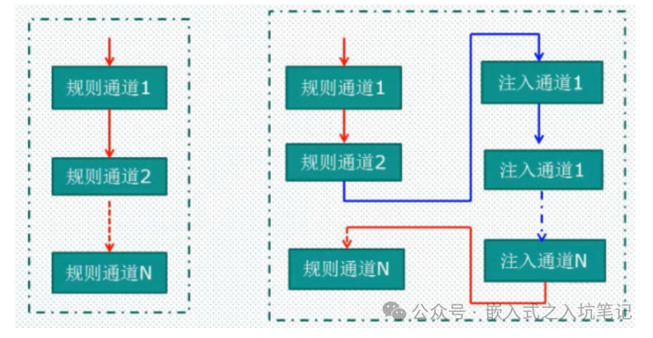
Note: The ADC is a 12-bit successive approximation analog-to-digital converter, with an output value range of 0 to 2^12 - 1 (0 to 4095), and a full scale of 3.3V. The resolution corresponds to the input voltage value of the least significant bit (LSB). Resolution = 3300/4095 ≈ 0.806mV.The STM32F10X series divides the ADC conversion into two channel groups: the regular channel group and the injected channel group. The regular channel operates like a normal running program, while the injected channel can interrupt the regular channel’s conversion. When the program is executing normally, interrupts can interrupt the program’s execution. Similarly, the conversion of the injected channel can interrupt the conversion of the regular channel, and only after the injected channel conversion is completed can the regular channel continue its conversion.
2. VOFA+
2.1 Introduction to VOFA+
VOFA+ is an intuitive, flexible, and powerful plugin-driven upper computer that can be seen in fields dealing with electrical systems, such as automation, embedded systems, the Internet of Things, and robotics. The name VOFA+ comes from: Volt, Ohm, Farad, Ampere, which are the basic units in the electrical field, named after their inventors—four giants in the field of electronic physics. The initials of their names together form the name VOFA+.
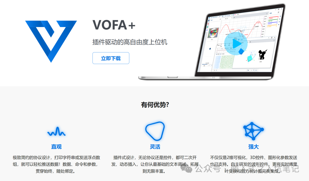
Overview of VOFA+ Features: Platform Support: Windows, Linux, MacOS; Interface Support: Serial (high baud rate, stable support), Network (TCP client/server, UDP); Protocol Support: Protocols are plugins, open source, anyone can write them. Currently supports CSV-style string protocols and hexadecimal floating-point array byte stream protocols; Control Support: Controls are plugins, open source, anyone can write them. Currently supports waveform graphs, buttons, status lights, images, sliders, 3D cube controls (model can be changed), etc.; Data Dimension Flexibility: 2D and 3D, both must be included; Self-developed waveform control: Supports drawing millions of sampling points per channel, with strong performance; Self-developed waveform control: Seamlessly integrates real-time histogram statistics and Fourier transforms with configurable point counts, allowing data analysis using VOFA+.2.2 How to Use VOFA+
VOFA+’s data protocol engine has three types: FireWater, JustFloat, RawData. Each data protocol engine has its own special effects, and readers can choose based on their actual needs. Here, the author mainly demonstrates the usage effects and methods of VOFA+ under the FireWater protocol.
The FireWater protocol is a CSV-style string stream, intuitive and simple, programming as easy as printf. However, since string parsing consumes more computational resources (both on the upper computer and the lower computer), it is recommended to use it only when the number of channels is not high and the sending frequency is not too high.
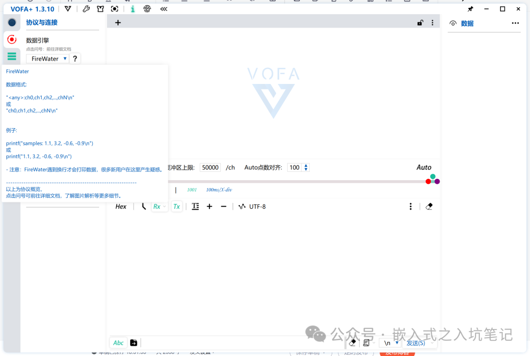
Hovering over the FireWater protocol provides helpful usage format assistance. As shown in the figure above, we use the printf(“simples:%f, %f\n”, sin(t1), sin(t2)) function for printing tests.
#include "math.h"<br/>#include "stdio.h"<br/>....<br/>int main(void){<br/> /* USER CODE BEGIN 1 */<br/> float t1 = 0;<br/> float t2 = 0;<br/> /* USER CODE END 1 */<br/>.......<br/> while (1) {<br/> /* USER CODE END WHILE */<br/> /* USER CODE BEGIN 3 */<br/> t1 += 0.1;<br/> t2 += 0.5;<br/> printf("simples:%f, %f\n", sin(t1), sin(t2));<br/> HAL_Delay(100);<br/> }<br/> /* USER CODE END 3 */<br/>}1. Select serial communication, port number, baud rate, and other parameter settings;
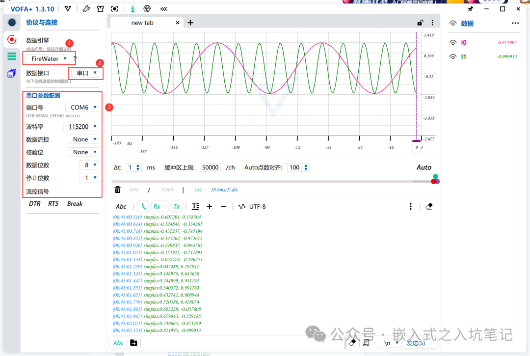
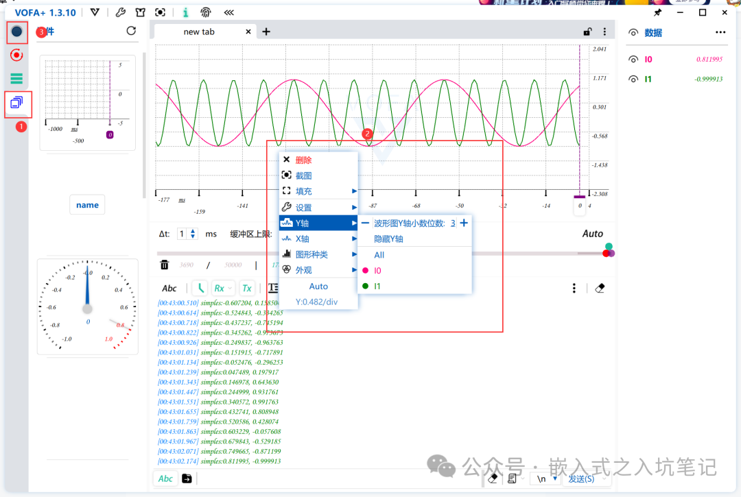
2. In the controls, select the waveform graph, drag it into the tab, right-click to select the Y-axis, and choose both inputs I0 and I1, then start the serial connection;
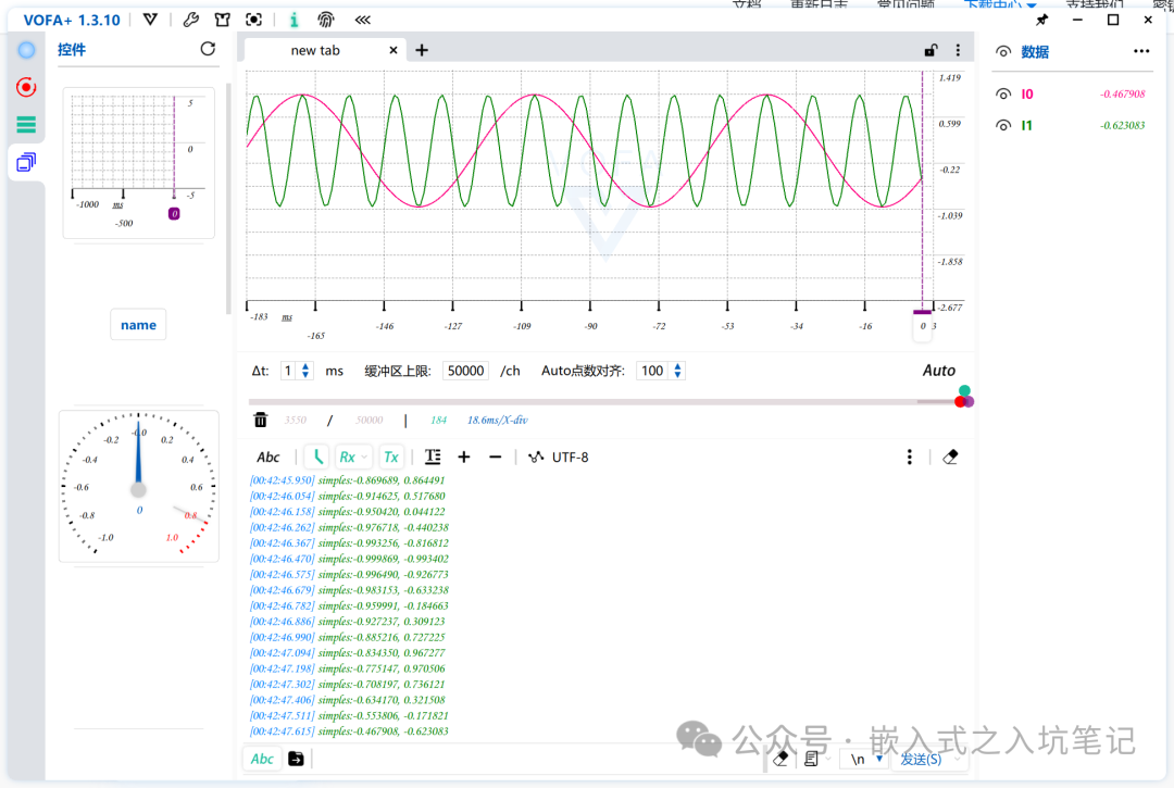
3. Run the upper computer and use the waveform graph control to read parameters from the lower computer;
3. Filtering Algorithms and Effects
Due to the inherent ADC peripheral defects of the MCU, its accuracy and stability are often poor, necessitating filtering compensation in many scenarios. The role of filtering is to reduce the impact of noise and interference on data measurement.3.1 Sampling without Filtering Algorithms
Directly sampling a voltage of 3.3V:
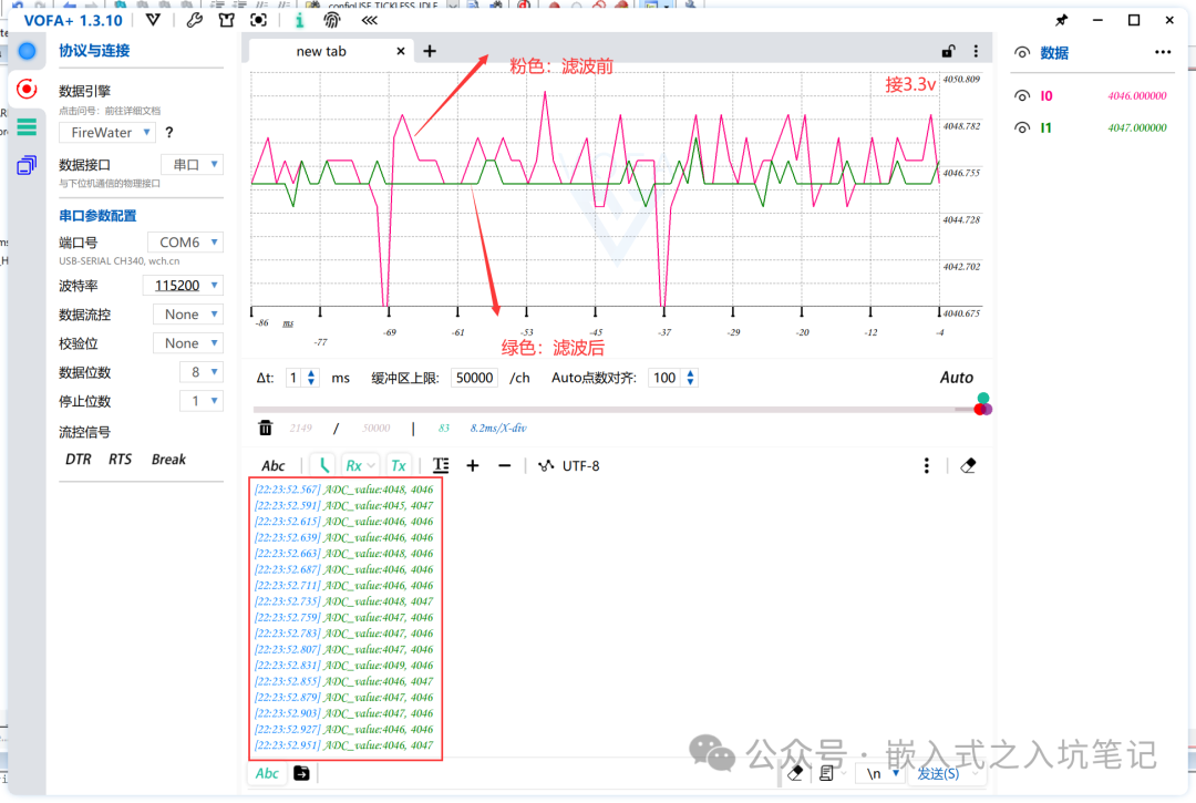
Data read by VOFA+:
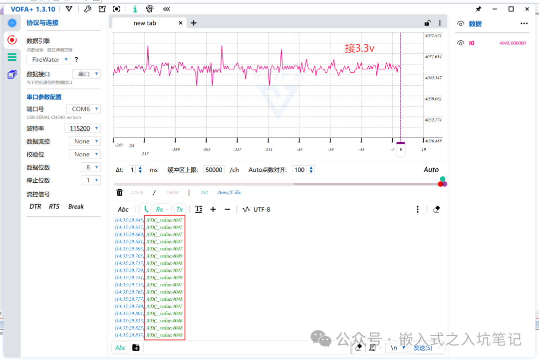
The above image clearly shows that the ADC sampling without filtering exhibits significant fluctuations. However, the author subjectively feels that the ADC of the F1 series seems to be more stable than that of the F4 series. (The reason it is not 4096 may be due to the power supply not reaching 3.3V).
4. Filtering Algorithms
4.1 First-Order Complementary Filter
Method: Take a=0~1, this filtering result = (1-a) * current sample value + a * previous filtering result<br/>Advantages: Good suppression of periodic interference, suitable for scenarios with high fluctuation frequencies<br/>Disadvantages: Phase lag, low sensitivity; the degree of lag depends on the value of a; cannot eliminate interference signals with frequencies higher than half the sampling frequency.The code is as follows:
// First-order complementary filter<br/>int firstOrderFilter(int newValue, int oldValue, float a){<br/> return a * newValue + (1-a) * oldValue;<br/>}<br/><br/>ADC_value=HAL_ADC_GetValue(&hadc1); // Get the value of ADC1<br/>// Main function<br/>while(1){<br/> HAL_ADC_Start(&hadc1); // Start ADC1, place in while loop<br/> Filtering_Value = firstOrderFilter(HAL_ADC_GetValue(&hadc1),ADC_value,0.3); // Filtering algorithm<br/> HAL_Delay(10); // Delay function to prevent sampling failure<br/> printf("ADC_value:%d\n", ADC_value);<br/>}Effect Diagram of VOFA+ Software:
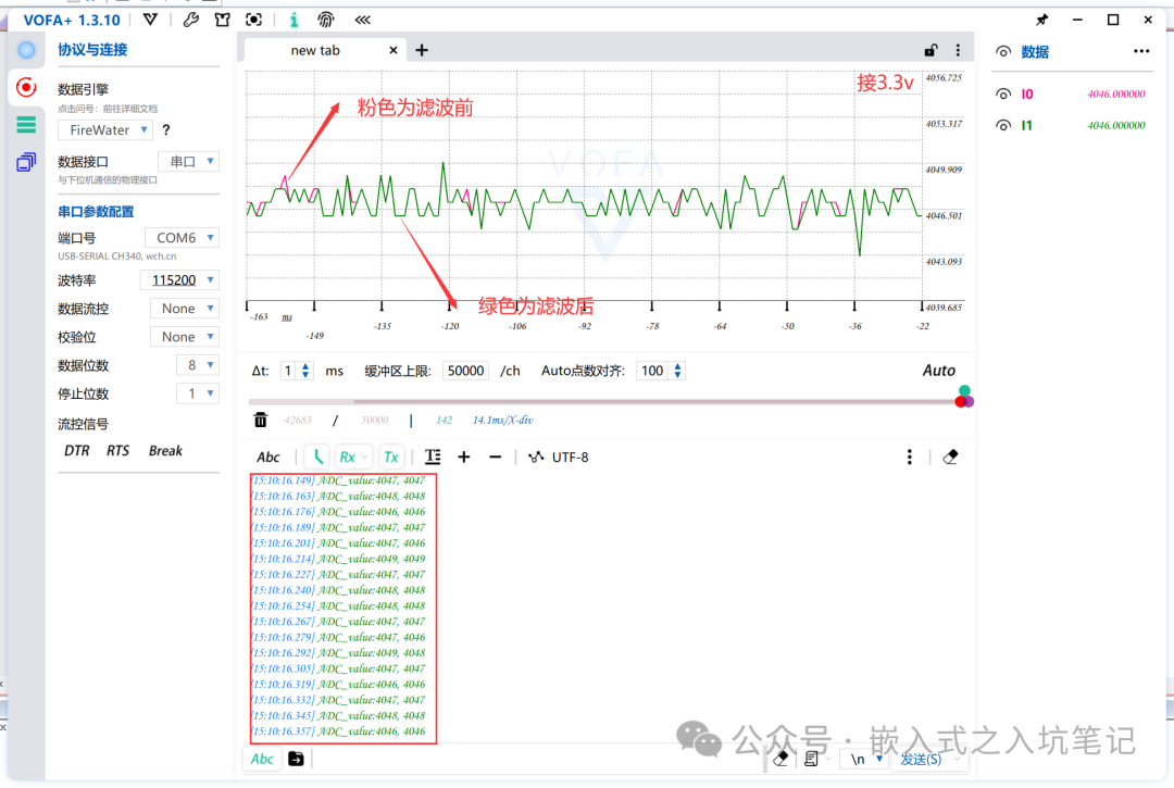
Conclusion:
The limitations of the first-order complementary filter are significant, and its effectiveness is quite average.4.2 Median Filtering
Method: Continuously sample N times (N should be odd), sort the N sampled values and take the middle value as the effective value<br/>Advantages: Effectively overcomes fluctuations caused by random factors; has good filtering effects for slowly changing measured parameters like temperature and liquid level<br/>Disadvantages: Not suitable for rapidly changing parameters like flow and speed.The code is as follows:
// Median filtering algorithm<br/>int middleValueFilter(int N){<br/> int value_buf[N];<br/> int i,j,k,temp;<br/> for( i = 0; i < N; ++i)<br/> {<br/> value_buf[i] = HAL_ADC_GetValue(&hadc1);<br/> }<br/> for(j = 0 ; j < N-1; ++j)<br/> {<br/> for(k = 0; k < N-j-1; ++k)<br/> {<br/> // Bubble sort from smallest to largest<br/> if(value_buf[k] > value_buf[k+1])<br/> {<br/> temp = value_buf[k];<br/> value_buf[k] = value_buf[k+1];<br/> value_buf[k+1] = temp;<br/> }<br/> }<br/> }<br/> return value_buf[(N-1)/2];<br/>}Effect Diagram of VOFA+ Software:
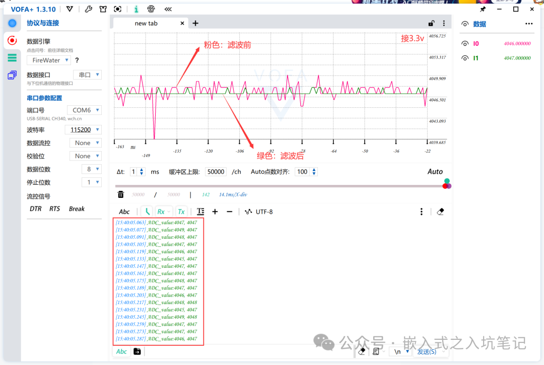
Conclusion:
Median filtering yields very effective results in eliminating outliers and stabilizing ADC sampling.4.3 Arithmetic Mean Filtering
Method: Continuously take N sampling values for arithmetic averaging; when N is large: higher signal smoothness but lower sensitivity; when N is small: lower signal smoothness but higher sensitivity; selection of N: generally for flow, N=12; for pressure, N=4<br/>Advantages: Suitable for filtering signals with random interference. Such signals have an average value and fluctuate around a certain range.<br/>Disadvantages: Not suitable for real-time control requiring fast data computation.The code is as follows:
// Arithmetic mean filtering<br/>int averageFilter(int N){<br/> int sum = 0;<br/> short i;<br/> for(i = 0; i < N; ++i)<br/> {<br/> sum += HAL_ADC_GetValue(&hadc1);<br/> }<br/> return sum/N;<br/>}Effect Diagram of VOFA+ Software:
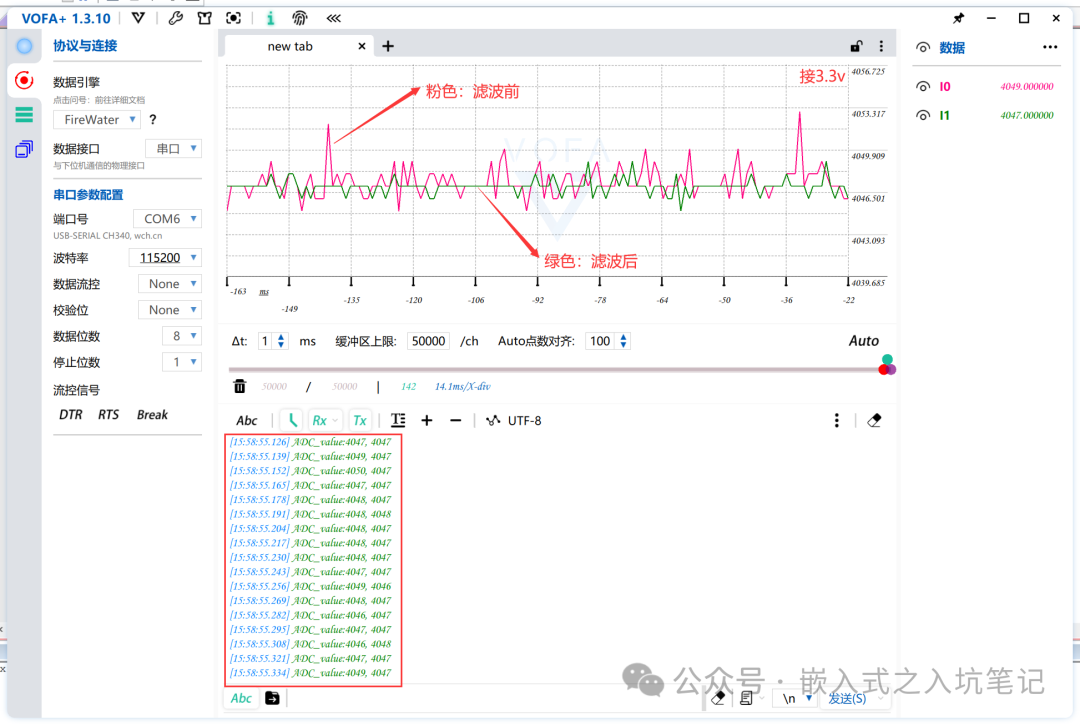
Conclusion:
Arithmetic mean filtering demonstrates a certain level of stability while exhibiting fluctuations (reasonable selection of N can yield good results).4.4 Moving Average Filtering
Method: Treat the continuously taken N sampling values as a queue, with a fixed length of N. Each time a new data point is sampled, it is added to the end of the queue, and the oldest data point is discarded (FIFO principle). The N data points in the queue are averaged to obtain the new filtering result. Selection of N: for flow, N=12; for pressure: N=4; for liquid level, N=4~12; for temperature, N=1~4<br/>Advantages: Good suppression of periodic interference, high smoothness; suitable for systems with high-frequency oscillations.<br/>Disadvantages: Low sensitivity; poor suppression of sporadic pulse interference; may waste RAM (improvement method: instead of discarding the oldest value, discard the last obtained average value).The code is as follows:
// Smooth average filtering<br/>#define N 10<br/>int value_buf[N];<br/>int sum=0;<br/>int curNum=0;<br/>int moveAverageFilter(){<br/> if(curNum < N)<br/> {<br/> value_buf[curNum] = HAL_ADC_GetValue(&hadc1);<br/> sum += value_buf[curNum];<br/> curNum++;<br/> return sum/curNum;<br/> }<br/> else<br/> {<br/> sum -= sum/N;<br/> sum += HAL_ADC_GetValue(&hadc1);<br/> return sum/N;<br/> }<br/>}Effect Diagram of VOFA+ Software:
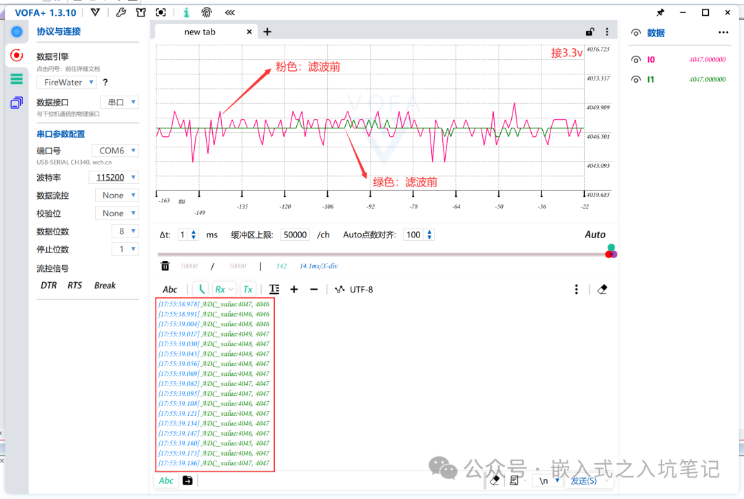
Conclusion:
Smooth average filtering, compared to ordinary arithmetic mean filtering, emphasizes smooth characteristics. The waveform graph from VOFA+ shows that smooth filtering can effectively counteract ADC sampling noise and stabilize collection (according to feedback from the author's peers, the effect of smooth filtering is very good, especially in control applications).4.5 Clipping Average Filtering
Method: Equivalent to "clipping filtering" + "recursive average filtering"; each time new data is sampled, it is first clipped before being sent to the queue for recursive average filtering.<br/>Advantages: Can eliminate sampling value deviations caused by sporadic pulse interference.<br/>Disadvantages: May waste RAM.The code is as follows:
// Clipping average filtering<br/>#define A 50 // Clipping amplitude threshold<br/>#define M 12<br/>int data[M];<br/>int First_flag=0;<br/>int LAverageFilter(){<br/> int i;<br/> int temp,sum,flag=0;<br/> data[0] = HAL_ADC_GetValue(&hadc1);<br/> for(i=1;i<M;i++)<br/> {<br/> temp=HAL_ADC_GetValue(&hadc1);<br/> if((temp-data[i-1])>A || ((data[i-1]-temp)>A))<br/> {<br/> i--; <br/> flag++;<br/> }<br/> else<br/> {<br/> data[i]=temp;<br/> }<br/> }<br/> for(i=0;i<M;i++)<br/> {<br/> sum+=data[i];<br/> }<br/> return sum/M;<br/>}Effect Diagram of VOFA+ Software:
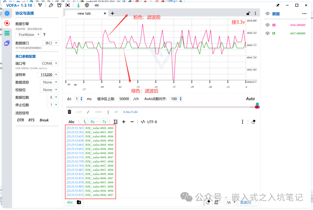
Conclusion:
Clipping average filtering is similar to a patchwork method, but its effects are significant. It effectively addresses the impact of sudden noise on ADC sampling in practical scenarios, although it consumes memory.4.6 Kalman Filtering
Core Idea: Based on the current instrument's "measured value" and the previous "predicted value" and "error", calculate the current optimal value, then predict the next value. A notable aspect is that it incorporates errors into the calculations, distinguishing between prediction errors and measurement errors, collectively referred to as noise. Another significant feature is that errors exist independently and are not influenced by measurement data.<br/>Advantages: Ingeniously integrates observed data with estimated data, managing errors in a closed loop, keeping them within a certain range. It has a wide applicability range and excellent timeliness and effectiveness.<br/>Disadvantages: Requires parameter tuning, as the size of parameters significantly affects filtering results.The code is as follows:
// Kalman filtering<br/>int KalmanFilter(int inData){<br/> static float prevData = 0; // Previous value<br/> static float p = 10, q = 0.001, r = 0.001, kGain = 0;<br/> // q controls error, r controls response speed<br/> p = p + q;<br/> kGain = p / ( p + r ); // Calculate Kalman gain<br/> inData = prevData + ( kGain * ( inData - prevData ) ); // Calculate this filtering estimate<br/> p = ( 1 - kGain ) * p; // Update measurement variance<br/> prevData = inData;<br/> return inData; // Return filtered value<br/>}Effect Diagram of VOFA+ Software:
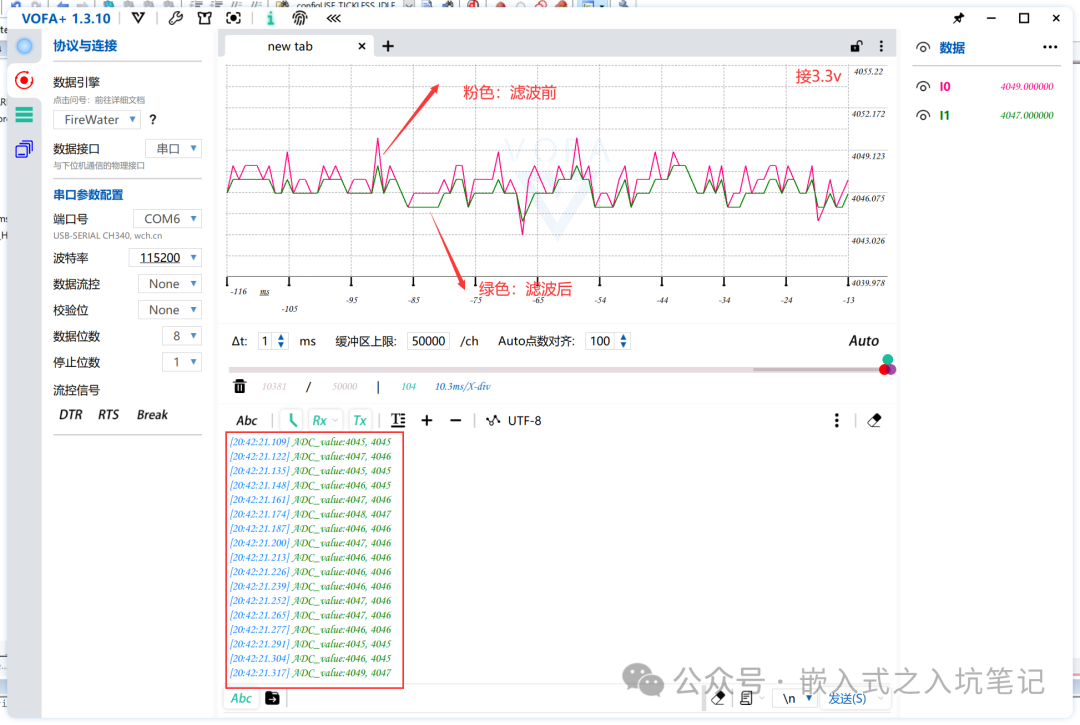
Conclusion:
The waveform graph displayed by VOFA+ shows that Kalman filtering has certain noise reduction and stabilization characteristics, although its effectiveness is not particularly outstanding. Kalman filtering is highly versatile, especially in control and multi-sensor fusion applications; as long as the parameters are well-tuned, the results can be surprisingly excellent.5. Experimental Summary
As an essential peripheral in embedded development, ADC often requires the setup of filters in projects. If the RC hardware filtering effect is average, software can be used to compensate. At the same time, there are various filtering algorithms, each with different principles. I hope readers do not blindly pursue various advanced filtering algorithms in actual engineering projects; the best filter is the one that suits the project.
Original Source:
Link: https://blog.csdn.net/black_sneak/article/details/129629485