Introduction
In microcontroller systems, the serial port (UART, Universal Asynchronous Receiver-Transmitter) is a very important component. Typically, the microcontroller’s serial port connects to the host computer via RS232/RS485 level conversion chips for data exchange, parameter settings, network composition, and connections to various external devices. The RS232/RS485 serial interface bus is characterized by low cost, simplicity, reliability, and ease of use, and due to its long history, it remains widely used today; especially in scenarios where data volume is not very large, serial communication is still a good choice with broad application prospects.
In microcontroller programming, the serial port plays a significant role. Traditionally, debugging serial port programs often involves using dedicated microcontroller hardware emulators. After writing the program, the emulator is used to set breakpoints, observe variables and program flow, and gradually debug the program to correct errors. While using a hardware emulator is indeed an effective method, it also has some drawbacks:
Many emulators cannot achieve complete hardware emulation, which can lead to situations where the emulation works correctly, but errors occur during actual operation; conversely, there are cases where the emulation fails, but the actual operation is normal.
For some newer chips or surface-mounted chips, either there are no suitable emulators or emulation heads available, or the hardware emulators are very expensive and not easily obtainable.
Sometimes, due to space limitations within the device’s internal structure, it is inconvenient to connect the emulation head.
Some emulators are simple online emulation types, which have many limitations during emulation. For example, they may have low speed, poor real-time performance or stability, and limitations on breakpoints, making emulation inconvenient.
1. Preparation Before Debugging
Here, we introduce a method to implement serial port debugging of user programs for the 51 microcontroller using the software simulation feature of Keil. With this method, no hardware emulator is required, and even the user circuit board is not needed. All that is required is:
① Hardware. A regular computer (with 2 standard serial ports) and a serial cable (both ends female, connection as shown in Figure 1).
② Serial port software can be custom debugging software or general serial communication software (such as Serial Assistant, Serial Debugger, etc.), mainly used for data transmission and reception. If suitable serial debugging software is not available, a free serial tool called TurboCom, written by the author, can be used. In addition to the data transmission and reception functions like other software, it also has two very useful features: timed alternating sending of custom data frames and automatic response (automatically returning the corresponding data frame after receiving a specified data frame), which is particularly suitable for aging tests. This tool can be downloaded online.
2. Introduction to Basic Debugging Commands
This serial port debugging method mainly utilizes the powerful software simulation capabilities of Keil. In the new version (above 6.0) of Keil software, the software simulation capabilities have been enhanced, allowing for more microcontroller functions to be simulated. Among these functions, one important feature is the ability to use the computer’s serial port to simulate the microcontroller’s serial port (this differs from many software that use stimulus files during simulation, allowing direct communication with other serial ports, making it more convenient and flexible). First, we will introduce the two commands needed during simulation: ASSIGN and MODE.
2.1 ASSIGN Command
Binds the microcontroller’s serial port to the computer’s serial port. The basic usage is:
ASSIGN channeloutreg
Where: channel represents the computer’s serial port, which can be COM1, COM2, COM3, or COM4; inreg and outreg represent the microcontroller’s serial port. For a standard microcontroller with only one serial port, they are SIN and SOUT; for microcontrollers with two or more serial ports, they are SnIN and SnOUT (n=0,1,… representing the microcontroller’s serial port number).
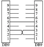
Figure 1 Serial Port Connection Diagram
For example:
ASSIGN COM1SOUT
Binds the computer’s serial port 1 to the microcontroller’s serial port (for microcontrollers with only one serial port).
ASSIGN COM2S0OUT
Binds the computer’s serial port 2 to the microcontroller’s serial port 0 (for microcontrollers with multiple serial ports, pay attention to the position of the serial port number).
It is important to note that the parentheses around the parameters cannot be omitted, while outreg does not have parentheses.
2.2 MODE Command
Sets the parameters of the bound computer serial port. The basic usage is:
MODE COMx baudrate, parity, databits, stopbits
Where: COMx (x = 1, 2, …) represents the computer’s serial port number; baudrate represents the baud rate of the serial port; parity represents the parity method; databits represents the data bit length; stopbits represents the stop bit length.
For example:
MODE COM1 9600, n, 8, 1
Sets serial port 1. Baud rate is 9600, no parity, 8 data bits, 1 stop bit.
MODE COM2 19200, 1, 8, 1
Sets serial port 2. Baud rate is 19200, odd parity, 8 data bits, 1 stop bit.
Using the above two commands, the computer’s serial port can be simulated as the microcontroller’s serial port. During software simulation, all data sent to the bound computer serial port will be forwarded to the Keil-simulated microcontroller serial port, and the user program can receive this data through interrupt handling or polling; similarly, data sent to the microcontroller’s serial port will also be sent out through the bound computer serial port and can be received by other software. Utilizing this feature, it is convenient to simulate and debug the serial port portion of the microcontroller program. It is important to note that these two commands need to be used together.
2.3 Simulation Steps
First, connect the two serial ports of the computer using a serial cable (or the two serial ports on two computers). One of these serial ports is used to simulate the microcontroller’s serial port, and the other is used for the debugging program. This allocation is up to the user, with no special requirements.
Next, write the user program and compile it successfully.
Then, set the relevant parameters of the project file (Project), as shown in Figures 2 and 3. The main tasks are to select the software simulation mode (Use Simulator) and set the oscillator parameters.
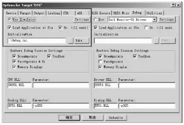
Figure 2 Simulation Parameter Settings
To avoid having to input the serial port parameter setting commands every time you enter simulation mode, you can create an initialization file. The initialization file is a regular text file, and the content consists of the commands needed during simulation, entered one per line in order. As shown in Figure 2, an initialization file named debug.ini has been created. This way, every time you enter simulation debugging mode, Keil will automatically load the contents of debug.ini for initialization.
To correctly simulate the serial port during software simulation debugging, the actual oscillator frequency used must also be set in the properties of the user’s Keil project file. This parameter is very important as it directly affects the communication baud rate and can be set according to the actual parameters used. Note that the unit of this parameter is MHz.
Once the parameters are set, you can proceed with the simulation. Click the icon on the toolbar to enter Debug (simulation debugging) mode in a new window, and in the command text box of the Output window (usually in the lower left corner), input the commands introduced above. For example, to set the PC’s serial port 1 as the microcontroller’s serial port:
mode com1 9600,0,8,1
assign com1 Sout
Then set breakpoints, usually at critical points or places associated with the serial port. Click the Run icon to run the user program, allowing it to operate (otherwise, serial data cannot be received). At this point, use the serial debugging software or user debugging software to send communication commands or data packets to see if the user program hits the breakpoints and whether the related variables are correct. You can also intentionally send data packets with erroneous data to observe whether the user program’s exception handling works correctly. If any errors are found in the program, you can immediately stop the simulation debugging, modify the code, and then repeat the above steps for simulation. Since there is no need to connect to the user target board or download code to the user board, the speed is very high. The above steps are fundamentally the same as those using a hardware emulator, except that now software simulation is used.
It is important to note that during simulation, the actual baud rate of the microcontroller’s serial port is specified by the MODE command, and parameters such as TMOD, SCON, etc., in the microcontroller program do not affect the serial port simulation state (meaning these parameters do not affect the simulation baud rate, even if they are incorrect). However, the interrupt enable bits (such as ES, EA, etc.) still take effect; if ES or EA is disabled, the serial port interrupt will not be triggered.
Since this method uses the computer’s serial port to simulate the microcontroller’s serial port, and the simulation is done through Keil software to convert the data on the serial port, rather than directly forwarding the data, the processing speed during actual simulation may be slightly lower than when the microcontroller is running. For example, in simulation mode, it may only send/receive 10 data frames in 1 second, while on the microcontroller hardware, it might be able to send/receive 50 data frames in the same time. This is related to the speed of the computer used, but it does not affect the simulation.
For microcontrollers with multiple serial ports, theoretically, multiple serial ports can be bound at once, as long as the computer has enough serial ports. Essentially, the number of computer serial ports required using this method is twice the number of serial ports bound to the microcontroller. One serial port is occupied by Keil to simulate the microcontroller’s serial port; the other serial port is occupied by the computer to send and receive data for the microcontroller’s serial port.
3. Conclusion
The method introduced here is suitable for both C51 and assembly language. Its greatest advantage is its simplicity, convenience, and ease of use, requiring no circuitry and having no special requirements; it can even allow the serial port portion of the program to be written and debugged before the hardware circuit is completed. The author has been using this method for a long time, and it has proven to be very effective. In fact, for the 51 microcontroller, the simulation capabilities of Keil are incredibly powerful; as long as one fully understands its features and can skillfully utilize it, most problems in work can be solved. Many tasks can be accomplished using software simulation without the need for any hardware emulator; only some timing and interface debugging of new external devices may require a hardware emulator. Currently, there are very few reference books on Keil software simulation, and some discuss older versions, but that is not a problem; the help files of Keil are very detailed and clear, and as long as one reads them carefully, they will be able to use it. Once proficient, one will find that Keil’s functionality is quite strong.
For serial port programming, the 51 microcontroller has the powerful development software Keil, which brings us great convenience; however, in the development of other microcontroller software, there are currently no such powerful development tools and convenient debugging methods. A workaround is to first write and debug the serial port program in Keil, and then port the program to other microcontroller platforms (the author has used this method in PIC18 microcontroller development with good results. Of course, this applies when developing microcontroller programs in C language; assembly language is not portable). As for how to reduce the workload of program porting and make the program more generic, allowing for smooth porting to other microcontroller platforms at minimal cost, is also a very worthwhile topic to explore.


Part of Electronic Book Screenshots

【Complete Set of Hardware Learning Materials Collection】